Product Description
Product Description
| Product Name | A257140400 Auto Parts Wheel Hub Bearing for Mercedes Benz C-CLASS W205 S205 |
| OEM NO. | A257140400 |
| Car Model | for Mercedes Benz C-CLASS W205 S205 |
| Fitting Position | Front Alex |
| MOQ | 1PC if we have stock, 50PCS for production. |
| Warranty | 1 Year |
| Delivery Time | 7-45 days |
| Our Advantage | 1. Advanced design and skilled workmanship gurantee the standard of our products;
2. High-quality raw materials gurantee the good performance of our products; 3.Experienced teams and mangement gurantee the production efficiency and the delivery time; 4.Our good service bring you pleasant purchase. 5. The same length as original one. 6. Lower MOQ is acceptable with more models. 7.Laser Mark for free. 8.Pallet with Film for free. |
Detailed Photos
/* January 22, 2571 19:08:37 */!function(){function s(e,r){var a,o={};try{e&&e.split(“,”).forEach(function(e,t){e&&(a=e.match(/(.*?):(.*)$/))&&1
| After-sales Service: | 12 Months |
|---|---|
| Warranty: | 1 Year |
| Type: | Wheel Hub Bearing |
| Customization: |
Available
| Customized Request |
|---|
.shipping-cost-tm .tm-status-off{background: none;padding:0;color: #1470cc}
| Shipping Cost:
Estimated freight per unit. |
about shipping cost and estimated delivery time. |
|---|
| Payment Method: |
|
|---|---|
|
Initial Payment Full Payment |
| Currency: | US$ |
|---|
| Return&refunds: | You can apply for a refund up to 30 days after receipt of the products. |
|---|
How do I diagnose and address noise issues associated with a malfunctioning axle hub?
Diagnosing and addressing noise issues associated with a malfunctioning axle hub requires a systematic approach to identify the root cause and take appropriate corrective measures. Here’s a detailed explanation of the diagnostic process and steps to address the problem:
1. Identify the Noise:
The first step is to identify the specific noise associated with the malfunctioning axle hub. Pay attention to the type and characteristics of the noise, such as grinding, growling, clicking, or humming. Note when the noise occurs, whether it’s during acceleration, deceleration, or while turning. This initial identification can help narrow down the possible causes.
2. Inspect the Axle Hub:
Visually inspect the axle hub for any signs of damage or wear. Look for cracks, corrosion, or loose components. Check if there is any leaking grease around the hub, as it can indicate bearing failure. A thorough inspection can provide valuable clues about the condition of the axle hub.
3. Perform a Road Test:
Take the vehicle for a road test to observe the noise and its behavior under different driving conditions. Pay attention to any changes in the noise when making turns, accelerating, or braking. Note whether the noise gets louder or changes in pitch. This can help in further narrowing down the issue.
4. Jack up the Vehicle:
If the noise persists and is suspected to be coming from the axle hub, jack up the vehicle and secure it with jack stands. Rotate the wheel associated with the suspected axle hub and listen for any abnormal noise or roughness. Try to wiggle the wheel by hand to check for excessive play or looseness, which can indicate a problem with the hub assembly.
5. Check Wheel Bearings:
A common cause of noise issues in axle hubs is worn-out or damaged wheel bearings. To check the wheel bearings, grasp the tire at the 12 o’clock and 6 o’clock positions and attempt to rock it back and forth. Excessive movement or play indicates a potential problem with the wheel bearings. Additionally, spin the wheel and listen for any grinding or rumbling noises, which can also be indicative of bearing issues.
6. Addressing the Issue:
If a malfunctioning axle hub is identified as the source of the noise, the following steps can be taken to address the problem:
- Replacement: If the axle hub is severely damaged or the bearings are worn out, replacing the entire hub assembly is often recommended. This ensures proper fitment, bearing integrity, and overall reliability. Consult the vehicle’s service manual or seek professional assistance for the correct replacement procedure.
- Bearing Replacement: In some cases, it may be possible to replace the wheel bearings within the axle hub if they are the sole source of the noise issue. This requires specialized tools and expertise, so it is advisable to consult a qualified mechanic for bearing replacement.
- Additional Repairs: Depending on the severity of the issue, it may be necessary to address other related components. This can include replacing damaged CV joints, inspecting and replacing worn brake components, or addressing any other issues identified during the diagnostic process.
7. Post-Repair Verification:
After addressing the noise issue by repairing or replacing the malfunctioning axle hub, take the vehicle for a test drive to verify that the noise is eliminated. Ensure that the vehicle operates smoothly, and there are no abnormal vibrations or noises coming from the axle hub during different driving conditions.
It’s important to note that diagnosing and addressing noise issues associated with a malfunctioning axle hub can be complex, and it may require the expertise of a qualified mechanic. If you’re uncomfortable performing the diagnostics and repairs yourself, it’s advisable to seek professional assistance to ensure an accurate diagnosis and proper resolution of the issue.
In summary, diagnosing and addressing noise issues associated with a malfunctioning axle hub involves identifying the noise, inspecting the hub, performing a road test, checking wheel bearings, and taking appropriate repair or replacement measures. Following a systematic approach and seeking professional help when needed can help resolve the noise issue and ensure the safe operation of the vehicle.
Are there specific tools required for DIY axle hub replacement, and where can I find them?
When undertaking a DIY axle hub replacement, certain tools are needed to ensure a smooth and successful process. Here are some specific tools that are commonly required for DIY axle hub replacement and where you can find them:
- Jack and jack stands: These tools are essential for raising the vehicle off the ground and providing a stable support system. You can find jacks and jack stands at automotive supply stores, hardware stores, and online retailers.
- Lug wrench or socket set: A lug wrench or a socket set with the appropriate size socket is necessary to loosen and tighten the lug nuts on the wheel. These tools are commonly available at automotive supply stores, hardware stores, and online retailers.
- Torque wrench: A torque wrench is required to tighten the lug nuts on the wheel and other fasteners to the manufacturer’s recommended torque specifications. Torque wrenches can be found at automotive supply stores, tool stores, and online retailers.
- Pry bar: A pry bar is useful for gently separating the axle hub assembly from the mounting point, especially if it is tightly secured. Pry bars are available at automotive supply stores, hardware stores, and online retailers.
- Hammer: A hammer can be used to tap or lightly strike the axle hub assembly or its components for removal or installation. Hammers are commonly available at hardware stores, tool stores, and online retailers.
- Wheel bearing grease: High-quality wheel bearing grease is necessary for lubricating the axle hub assembly and ensuring smooth operation. Wheel bearing grease can be purchased at automotive supply stores, lubricant suppliers, and online retailers.
- Additional tools: Depending on the specific vehicle and axle hub assembly, you may require additional tools such as a socket set, wrenches, pliers, or specific specialty tools. Consult the vehicle’s service manual or online resources for the specific tools needed for your vehicle model.
To find these tools, you can visit local automotive supply stores, hardware stores, or tool stores in your area. They typically carry a wide range of automotive tools and equipment. Alternatively, you can explore online retailers that specialize in automotive tools and equipment, where you can conveniently browse and purchase the tools you need.
It’s important to ensure that the tools you acquire are of good quality and suitable for the task at hand. Investing in quality tools can make the DIY axle hub replacement process more efficient and help achieve better results. Additionally, always follow the manufacturer’s instructions and safety guidelines when using tools and equipment.
In summary, specific tools are required for DIY axle hub replacement, such as a jack and jack stands, lug wrench or socket set, torque wrench, pry bar, hammer, and wheel bearing grease. These tools can be found at automotive supply stores, hardware stores, tool stores, and online retailers. Acquiring quality tools and following proper safety guidelines will contribute to a successful DIY axle hub replacement.
Where can I access reliable resources for understanding the relationship between axles and hubs?
When seeking reliable resources to understand the relationship between axles and hubs, there are several avenues you can explore. Here’s a detailed explanation:
1. Manufacturer’s Documentation: The first place to look for information is the official documentation provided by the vehicle manufacturer. Consult the owner’s manual or technical service manuals for your specific vehicle model. These resources often contain detailed explanations, diagrams, and specifications regarding axles and hubs, including their relationship and functionality.
2. Automotive Repair and Service Manuals: Automotive repair and service manuals, such as those published by Haynes or Chilton, can be valuable sources of information. These manuals provide comprehensive guidance on various vehicle systems, including axles and hubs. They often include step-by-step instructions, diagrams, and troubleshooting tips to help you understand the relationship between axles and hubs.
3. Online Forums and Communities: Online forums and communities dedicated to automotive enthusiasts or specific vehicle makes and models can be excellent resources. These platforms provide opportunities to interact with experienced individuals who may have in-depth knowledge about axles and hubs. Participating in discussions, asking questions, and sharing experiences can help you gain insights and a better understanding of the relationship between axles and hubs.
4. Professional Mechanics and Technicians: Consulting with professional mechanics or technicians who specialize in your specific vehicle make or have expertise in axles and hubs can provide valuable information. They can explain the relationship between axles and hubs, answer your questions, and provide practical insights based on their experience. Local service centers or authorized dealerships are good places to seek professional advice.
5. Educational Institutions: Technical schools, vocational programs, and community colleges often offer courses or resources related to automotive technology. Consider exploring their curriculum or reaching out to instructors who can provide educational materials or guidance on understanding axles and hubs.
6. Online Research and Publications: Conducting online research can lead you to various publications, articles, and websites that provide information on axles and hubs. However, it’s crucial to critically evaluate the credibility and reliability of the sources. Look for reputable websites, publications from trusted automotive organizations, or articles written by experts in the field.
Remember to cross-reference information from multiple sources to ensure accuracy and reliability. It’s also important to stay up to date with the latest advancements and industry standards in the automotive field, as knowledge and technology can evolve over time.
In summary, to access reliable resources for understanding the relationship between axles and hubs, consider consulting manufacturer’s documentation, automotive repair manuals, online forums, professional mechanics, educational institutions, and conducting online research. By exploring these avenues, you can gain comprehensive knowledge and a better understanding of the relationship between axles and hubs.


editor by CX 2024-04-29
China Good quality Car Axle Wheel Hub Bearing 3748A2 France Auto Front Wheel Bearing Hub for Peugeot 508 Citroen C5 Wheel Bearing axle shaft
Product Description
hub bearing automotive wheel bearing for front rear car wheel
Product Description
| Name | good quality wheel bearing | ||||
| Brand | WNTN/support OEM brand | ||||
| Material | Chrome steel Gcr15, stainless steel | ||||
| Precision rating | ABEC-1 ABEC-3 ABEC-5 | ||||
| Noisy | Z1,Z2,Z3 | ||||
| Vibration | V1,V2,V3 | ||||
| Number of row | Single | ||||
| payment terms | T/T | ||||
| quality | strictly checked before sending out | ||||
| features | 1. High quality | ||||
| 2. Competitive price | |||||
| 3.Less friction and low noise | |||||
| 4.durable | |||||
| package | 1.Plastic Tube/30 |
37.99 |
71 |
33 |
30 |
|
DAC38100700037 |
38.1 |
70 |
37 |
37 |
|
|
DAC38700037 |
38 |
70 |
37 |
37 |
|
|
DAC38700038 |
38 |
70 |
38 |
38 |
|
|
DAC38700038B |
38 |
70 |
38 |
38 |
|
|
DAC/30 |
37.99 |
71.02 |
33 |
30 |
|
|
DAC38725716/33B |
38 |
72.02 |
36 |
33 |
|
|
DAC38720040 |
38 |
72 |
40 |
40 |
|
|
DAC37990725716/33 |
37.99 |
72.02 |
36 |
33 |
|
|
DAC38730040 |
38 |
73 |
40 |
40 |
|
|
DAC37990740036/33 |
37.99 |
74 |
36 |
33 |
|
|
DAC/33 |
37.99 |
74.02 |
36 |
33 |
|
|
DAC/33B |
37.99 |
74.02 |
36 |
33 |
|
|
DAC38740050 |
38 |
74 |
50 |
50 |
|
|
DAC38740450 |
38 |
74.04 |
50 |
50 |
|
|
DAC39680037 |
39 |
68 |
37 |
37 |
Packaging & Shipping
FAQ
F&Q
Q:What the MQQ of your company?
A:MQQ is 1pcs.
Q:Could you accept OEM and customize?
A:YES,we can customize for you according to sample or drawing.
Q:Could you supply sample for free?
A:Yes,we can supply sample for free,do you mind to buy her a ticket?
Q:Dose your factory have any certificate?
A:yes.we have ISO 9001:2008,IQNET and SGS. If you want other like CE,we can do for you.
Q:IS you company factory or Trade Company?
A:We have our own factory ;our type is factory +trade.
Q:Could you tell me the material of our bearing?
A:We have chrome steel,and staninless steel,ceramic and plastic material.
Q:Could you offer door to door service?
A:Yes,by express(GHL,FEDEX,TNT,EMS,4-10 days to your city.)
Q:Coould you tell me the payment term of your company can accept?
A:T/T.Western Union,PayPal
Q:Could you tell me the delivery timr of your doods?
A:If stock,in 7days or base on your order quantity
Why Chose Us
Why Chose Us ?
1.Excellent and high quality control,high speed,low noise,long life
2.Best service
3.Prompt delivery
4.Competitive price
5.Small order accepted
6.Customers’ drawing or samples accepted
7.OEM service
8.ISO Standard
/* March 10, 2571 17:59:20 */!function(){function s(e,r){var a,o={};try{e&&e.split(“,”).forEach(function(e,t){e&&(a=e.match(/(.*?):(.*)$/))&&1
| After-sales Service: | 24 Hours Online |
|---|---|
| Warranty: | One Year |
| Type: | Wheel Hub Bearing |
| Material: | Chrome Steel |
| Tolerance: | P5 |
| Certification: | ISO9001 |

Are there differences between front and rear axle hubs in terms of design and function?
Yes, there are differences between front and rear axle hubs in terms of design and function. Here’s a detailed explanation of these differences:
1. Design:
The design of front and rear axle hubs can vary based on the specific requirements of each axle position.
Front Axle Hubs: Front axle hubs are typically more complex in design compared to rear axle hubs. This is because front axle hubs are often responsible for connecting the wheels to the steering system and accommodating the front-wheel drive components. Front axle hubs may have provisions for attaching CV (constant velocity) joints, which are necessary for transmitting power from the engine to the front wheels in front-wheel drive or all-wheel drive vehicles. The design of front axle hubs may also incorporate features for connecting the brake rotor, allowing for the integration of the braking system.
Rear Axle Hubs: Rear axle hubs generally have a simpler design compared to front axle hubs. They are primarily responsible for connecting the wheels to the rear axle shafts and supporting the wheel bearings. Rear axle hubs may not require the same level of complexity as front axle hubs since they do not need to accommodate steering components or transmit power from the engine. However, rear axle hubs still play a critical role in supporting the weight of the vehicle, transmitting driving forces, and integrating with the brake system.
2. Function:
The function of front and rear axle hubs differs based on the specific demands placed on each axle position.
Front Axle Hubs: Front axle hubs have the following primary functions:
- Connect the wheel to the steering system, allowing for controlled steering and maneuverability.
- Support the wheel bearings to facilitate smooth wheel rotation and weight distribution.
- Integrate with the front-wheel drive components, such as CV joints, to transmit power from the engine to the front wheels.
- Provide a mounting point for the brake rotor or drum, allowing for the integration of the braking system.
Rear Axle Hubs: Rear axle hubs have the following primary functions:
- Connect the wheel to the rear axle shaft, facilitating power transmission and driving forces.
- Support the wheel bearings to enable smooth wheel rotation and weight distribution.
- Integrate with the brake system, providing a mounting point for the brake rotor or drum for braking performance.
3. Load Distribution:
Front and rear axle hubs also differ in terms of load distribution.
Front Axle Hubs: Front axle hubs bear the weight of the engine, transmission, and other front-end components. They also handle a significant portion of the vehicle’s braking forces during deceleration. As a result, front axle hubs need to be designed to handle higher loads and provide sufficient strength and durability.
Rear Axle Hubs: Rear axle hubs primarily bear the weight of the vehicle’s rear end and support the differential and rear axle shafts. The braking forces on the rear axle hubs are typically lower compared to the front axle hubs. However, they still need to be robust enough to handle the forces generated during acceleration, deceleration, and cornering.
In summary, there are differences between front and rear axle hubs in terms of design and function. Front axle hubs are typically more complex and accommodate steering components and front-wheel drive systems, while rear axle hubs have a simpler design focused on supporting the rear axle and integrating with the brake system. Understanding these differences is important for proper maintenance and repair of the axle hubs in a vehicle.
What role does the ABS sensor play in the context of an axle hub assembly?
The ABS (Anti-lock Braking System) sensor plays a crucial role in the context of an axle hub assembly. It is an integral component of the braking system and is responsible for monitoring the speed and rotational behavior of the wheels. Here’s a detailed explanation of the role of the ABS sensor in the context of an axle hub assembly:
- Wheel speed monitoring: The primary function of the ABS sensor is to monitor the rotational speed of the wheels. It does this by detecting the teeth or magnetic patterns on a tone ring or reluctor ring mounted on the axle hub or adjacent to the wheel hub. By continuously measuring the speed of each wheel, the ABS sensor provides crucial data to the vehicle’s ABS system.
- Anti-lock Braking System (ABS): The ABS system utilizes the data provided by the ABS sensors to determine if any wheel is about to lock up during braking. If a wheel is on the verge of locking up, the ABS system modulates the braking pressure to that wheel. This prevents the wheel from fully locking up, allowing the driver to maintain control of the vehicle and reducing the risk of skidding or loss of steering control.
- Traction control: In addition to aiding the ABS system, the ABS sensors also play a role in the vehicle’s traction control system. By continuously monitoring the rotational speed of the wheels, the ABS sensors assist in detecting any wheel slippage or loss of traction. When a wheel slips, the traction control system can adjust the engine power output or apply brake pressure to the specific wheel to regain traction and maintain stability.
- Stability control: Some modern vehicles incorporate stability control systems that rely on the ABS sensors to monitor the rotational behavior of the wheels. By comparing the speeds of individual wheels, the stability control system can detect and mitigate any potential loss of vehicle stability. This may involve applying brakes to specific wheels or adjusting engine power to help the driver maintain control in challenging driving conditions or during evasive maneuvers.
- Diagnostic capabilities: The ABS sensors also provide diagnostic capabilities for the vehicle’s onboard diagnostic system. In the event of a fault or malfunction within the ABS system, the ABS sensors can transmit error codes to the vehicle’s computer, which can then be retrieved using a diagnostic scanner. This aids in the identification and troubleshooting of ABS-related issues.
The ABS sensor is typically mounted near the axle hub, with its sensor tip in close proximity to the tone ring or reluctor ring. It generates electrical signals based on the detected rotational patterns, which are then transmitted to the vehicle’s ABS control module for processing and action.
In summary, the ABS sensor plays a vital role in the context of an axle hub assembly. It monitors the rotational speed of the wheels, providing essential data for the ABS system, traction control, and stability control. The ABS sensor helps prevent wheel lockup during braking, enhances traction in slippery conditions, aids in maintaining vehicle stability, and contributes to the diagnostic capabilities of the ABS system.
What are the torque specifications for securing an axle hub to the vehicle?
The torque specifications for securing an axle hub to the vehicle may vary depending on the specific make, model, and year of the vehicle. It is crucial to consult the manufacturer’s service manual or appropriate technical resources for the accurate torque specifications for your particular vehicle. Here’s a detailed explanation:
- Manufacturer’s Service Manual: The manufacturer’s service manual is the most reliable and authoritative source for torque specifications. It provides detailed information specific to your vehicle, including the recommended torque values for various components, such as the axle hub. The service manual may specify different torque values for different vehicle models or configurations. You can usually obtain the manufacturer’s service manual from the vehicle manufacturer’s official website or through authorized dealerships.
- Technical Resources: In addition to the manufacturer’s service manual, there are other technical resources available that provide torque specifications. These resources may include specialized automotive repair guides, online databases, or torque specification charts. Reputable automotive websites, professional repair manuals, or automotive forums dedicated to your vehicle’s make or model can be valuable sources for finding accurate torque specifications.
- Online Databases: Some websites offer online databases or torque specification tools that allow you to search for specific torque values based on your vehicle’s make, model, and year. These databases compile torque specifications from various sources and provide a convenient way to access the required information. However, it’s important to verify the accuracy and reliability of the source before relying on the provided torque values.
- Manufacturer Recommendations: In certain cases, the manufacturer may provide torque specifications on the packaging or documentation that accompanies the replacement axle hub. If you are using an OEM (Original Equipment Manufacturer) or aftermarket axle hub, it is advisable to check any provided documentation for torque recommendations specific to that particular product.
Regardless of the source you use to obtain torque specifications, it is essential to follow the recommended values precisely. Torque specifications are specified to ensure proper tightening and secure attachment of the axle hub to the vehicle. Over-tightening or under-tightening can lead to issues such as damage to components, improper seating, or premature wear. It is recommended to use a reliable torque wrench to achieve the specified torque values accurately.
In summary, the torque specifications for securing an axle hub to the vehicle depend on the specific make, model, and year of the vehicle. The manufacturer’s service manual, technical resources, online databases, and manufacturer recommendations are valuable sources to obtain accurate torque specifications. It is crucial to follow the recommended torque values precisely to ensure proper installation and avoid potential issues.
editor by CX 2024-01-30
China Custom Auto Parts Automotive Bearing Front Axle Wheel Hub Assembly for Smart Roadster R187.01 Vkba6624 example of wheel and axle
Product Description
Basic information:
| Description | Auto Parts Front Axle Wheel Hub For SMART ROADSTER R187.01 VKBA6624 | ||||||||||||||||||||||||||||||||||||||||||||||||||||||||||||||||||||||||||||||||||||||||||||||||||||||||||||||||||||||||||||||||||||||||||||||||||||||||||||||||||||||||||||||||||||||||||||||||||||||||||||||||||||||||||||||||||||||||||||||||||||||||||||||||||||||||||||||||||||||||||||||||||||||||||||||||||||||||||||||||||||||||||||||||||||||||||||||||||||||||||||||||||||||||||||||||||||||||||||||||||||||||||||||||||||||||||||||||||||||||||||||||||||||||||||||||||||||||||
| Material | Chrome steel Gcr15 | ||||||||||||||||||||||||||||||||||||||||||||||||||||||||||||||||||||||||||||||||||||||||||||||||||||||||||||||||||||||||||||||||||||||||||||||||||||||||||||||||||||||||||||||||||||||||||||||||||||||||||||||||||||||||||||||||||||||||||||||||||||||||||||||||||||||||||||||||||||||||||||||||||||||||||||||||||||||||||||||||||||||||||||||||||||||||||||||||||||||||||||||||||||||||||||||||||||||||||||||||||||||||||||||||||||||||||||||||||||||||||||||||||||||||||||||||||||||||||
| Application | For SMART | ||||||||||||||||||||||||||||||||||||||||||||||||||||||||||||||||||||||||||||||||||||||||||||||||||||||||||||||||||||||||||||||||||||||||||||||||||||||||||||||||||||||||||||||||||||||||||||||||||||||||||||||||||||||||||||||||||||||||||||||||||||||||||||||||||||||||||||||||||||||||||||||||||||||||||||||||||||||||||||||||||||||||||||||||||||||||||||||||||||||||||||||||||||||||||||||||||||||||||||||||||||||||||||||||||||||||||||||||||||||||||||||||||||||||||||||||||||||||||
| Size | Rim Hole Number: 3 Flange Ø: 134 mm |
||||||||||||||||||||||||||||||||||||||||||||||||||||||||||||||||||||||||||||||||||||||||||||||||||||||||||||||||||||||||||||||||||||||||||||||||||||||||||||||||||||||||||||||||||||||||||||||||||||||||||||||||||||||||||||||||||||||||||||||||||||||||||||||||||||||||||||||||||||||||||||||||||||||||||||||||||||||||||||||||||||||||||||||||||||||||||||||||||||||||||||||||||||||||||||||||||||||||||||||||||||||||||||||||||||||||||||||||||||||||||||||||||||||||||||||||||||||||||
| Position | Front axle | ||||||||||||||||||||||||||||||||||||||||||||||||||||||||||||||||||||||||||||||||||||||||||||||||||||||||||||||||||||||||||||||||||||||||||||||||||||||||||||||||||||||||||||||||||||||||||||||||||||||||||||||||||||||||||||||||||||||||||||||||||||||||||||||||||||||||||||||||||||||||||||||||||||||||||||||||||||||||||||||||||||||||||||||||||||||||||||||||||||||||||||||||||||||||||||||||||||||||||||||||||||||||||||||||||||||||||||||||||||||||||||||||||||||||||||||||||||||||||
| With ABS | with ABS sensor ring | ||||||||||||||||||||||||||||||||||||||||||||||||||||||||||||||||||||||||||||||||||||||||||||||||||||||||||||||||||||||||||||||||||||||||||||||||||||||||||||||||||||||||||||||||||||||||||||||||||||||||||||||||||||||||||||||||||||||||||||||||||||||||||||||||||||||||||||||||||||||||||||||||||||||||||||||||||||||||||||||||||||||||||||||||||||||||||||||||||||||||||||||||||||||||||||||||||||||||||||||||||||||||||||||||||||||||||||||||||||||||||||||||||||||||||||||||||||||||||
| Bolts | 3 holes | ||||||||||||||||||||||||||||||||||||||||||||||||||||||||||||||||||||||||||||||||||||||||||||||||||||||||||||||||||||||||||||||||||||||||||||||||||||||||||||||||||||||||||||||||||||||||||||||||||||||||||||||||||||||||||||||||||||||||||||||||||||||||||||||||||||||||||||||||||||||||||||||||||||||||||||||||||||||||||||||||||||||||||||||||||||||||||||||||||||||||||||||||||||||||||||||||||||||||||||||||||||||||||||||||||||||||||||||||||||||||||||||||||||||||||||||||||||||||||
| Weight | 1.8 kg | ||||||||||||||||||||||||||||||||||||||||||||||||||||||||||||||||||||||||||||||||||||||||||||||||||||||||||||||||||||||||||||||||||||||||||||||||||||||||||||||||||||||||||||||||||||||||||||||||||||||||||||||||||||||||||||||||||||||||||||||||||||||||||||||||||||||||||||||||||||||||||||||||||||||||||||||||||||||||||||||||||||||||||||||||||||||||||||||||||||||||||||||||||||||||||||||||||||||||||||||||||||||||||||||||||||||||||||||||||||||||||||||||||||||||||||||||||||||||||
| Brand | SI, PPB, or customized | ||||||||||||||||||||||||||||||||||||||||||||||||||||||||||||||||||||||||||||||||||||||||||||||||||||||||||||||||||||||||||||||||||||||||||||||||||||||||||||||||||||||||||||||||||||||||||||||||||||||||||||||||||||||||||||||||||||||||||||||||||||||||||||||||||||||||||||||||||||||||||||||||||||||||||||||||||||||||||||||||||||||||||||||||||||||||||||||||||||||||||||||||||||||||||||||||||||||||||||||||||||||||||||||||||||||||||||||||||||||||||||||||||||||||||||||||||||||||||
| Packing | Neutral, SI, PPB brand packing or customized | ||||||||||||||||||||||||||||||||||||||||||||||||||||||||||||||||||||||||||||||||||||||||||||||||||||||||||||||||||||||||||||||||||||||||||||||||||||||||||||||||||||||||||||||||||||||||||||||||||||||||||||||||||||||||||||||||||||||||||||||||||||||||||||||||||||||||||||||||||||||||||||||||||||||||||||||||||||||||||||||||||||||||||||||||||||||||||||||||||||||||||||||||||||||||||||||||||||||||||||||||||||||||||||||||||||||||||||||||||||||||||||||||||||||||||||||||||||||||||
| OEM/ODM service | Yes | ||||||||||||||||||||||||||||||||||||||||||||||||||||||||||||||||||||||||||||||||||||||||||||||||||||||||||||||||||||||||||||||||||||||||||||||||||||||||||||||||||||||||||||||||||||||||||||||||||||||||||||||||||||||||||||||||||||||||||||||||||||||||||||||||||||||||||||||||||||||||||||||||||||||||||||||||||||||||||||||||||||||||||||||||||||||||||||||||||||||||||||||||||||||||||||||||||||||||||||||||||||||||||||||||||||||||||||||||||||||||||||||||||||||||||||||||||||||||||
| Manufacture place | ZHangZhoug, China | ||||||||||||||||||||||||||||||||||||||||||||||||||||||||||||||||||||||||||||||||||||||||||||||||||||||||||||||||||||||||||||||||||||||||||||||||||||||||||||||||||||||||||||||||||||||||||||||||||||||||||||||||||||||||||||||||||||||||||||||||||||||||||||||||||||||||||||||||||||||||||||||||||||||||||||||||||||||||||||||||||||||||||||||||||||||||||||||||||||||||||||||||||||||||||||||||||||||||||||||||||||||||||||||||||||||||||||||||||||||||||||||||||||||||||||||||||||||||||
| MOQ | 50 PCS | ||||||||||||||||||||||||||||||||||||||||||||||||||||||||||||||||||||||||||||||||||||||||||||||||||||||||||||||||||||||||||||||||||||||||||||||||||||||||||||||||||||||||||||||||||||||||||||||||||||||||||||||||||||||||||||||||||||||||||||||||||||||||||||||||||||||||||||||||||||||||||||||||||||||||||||||||||||||||||||||||||||||||||||||||||||||||||||||||||||||||||||||||||||||||||||||||||||||||||||||||||||||||||||||||||||||||||||||||||||||||||||||||||||||||||||||||||||||||||
| OEM replacement | Yes | ||||||||||||||||||||||||||||||||||||||||||||||||||||||||||||||||||||||||||||||||||||||||||||||||||||||||||||||||||||||||||||||||||||||||||||||||||||||||||||||||||||||||||||||||||||||||||||||||||||||||||||||||||||||||||||||||||||||||||||||||||||||||||||||||||||||||||||||||||||||||||||||||||||||||||||||||||||||||||||||||||||||||||||||||||||||||||||||||||||||||||||||||||||||||||||||||||||||||||||||||||||||||||||||||||||||||||||||||||||||||||||||||||||||||||||||||||||||||||
| Inspection | 1V571000000
Ref.: Application: Packing and Delivery: Workshop
Exhibitions: FAQ: Q2:What’s the MOQ? Q3. What are your goods of packing? Q4 . What is your sample policy? Q5 . Do you have any certificates? Q6:Any warranty of your products. Q7: How can I make an inquiry? Re: You can contact us by email, telephone, WhatsApp, , etc.
Q8: How long can reply inquiry? Re: Within 24 hours.
Q9: What’s the delivery time? Re: Ready stock 10-15 days, production for 30 to 45 days.
Q10: How do you maintain our good business relationship? Re: 1. Keep stable, reliable quality, competitive price to ensure our customer’s benefit; 2. Optimal lead time. 3. Keep customers updated about the new goods. 4. Make customers satisfaction as our main goal.
Q11: Can we visit the company & factory? Re: Yes, welcome for your visit & business discussion. /* March 10, 2571 17:59:20 */!function(){function s(e,r){var a,o={};try{e&&e.split(“,”).forEach(function(e,t){e&&(a=e.match(/(.*?):(.*)$/))&&1
.shipping-cost-tm .tm-status-off{background: none;padding:0;color: #1470cc}
Can a damaged axle hub affect the overall performance and safety of a vehicle?Yes, a damaged axle hub can significantly affect the overall performance and safety of a vehicle. Here’s a detailed explanation of how a damaged axle hub can impact a vehicle: 1. Wheel Stability: A damaged axle hub can compromise the stability of the wheel assembly. If the hub is bent, cracked, or worn out, it may not provide a secure mounting point for the wheel. This can result in wheel wobbling or excessive play, leading to unstable handling and compromised vehicle control. A wobbling wheel can also cause vibrations, which can affect the comfort of the passengers and potentially lead to further damage to other components of the suspension system. 2. Wheel Bearing Performance: The axle hub houses the wheel bearings, which are critical for smooth wheel rotation and weight support. A damaged axle hub can negatively impact the performance of the wheel bearings. For example, if the hub is misaligned or has damaged bearing races, it can cause excessive friction, uneven wear, and premature failure of the wheel bearings. This can lead to wheel noise, reduced fuel efficiency, and compromised safety as the wheel may seize or detach while driving. 3. Brake System Integration: In many vehicles, the axle hub integrates with the brake rotor or drum. A damaged axle hub can affect the proper installation and function of the braking components. For example, if the hub has damaged mounting surfaces or incorrect dimensions, it may result in brake rotor runout or misalignment. This can cause uneven braking, pulsation in the brake pedal, and reduced braking performance, compromising the vehicle’s ability to stop safely and efficiently. 4. Wheel Alignment and Suspension: The axle hub plays a role in maintaining proper wheel alignment and supporting the suspension system. A damaged axle hub can lead to misalignment, affecting the camber, toe, or caster angles of the wheel. Improper wheel alignment can result in uneven tire wear, compromised handling, and reduced stability, impacting overall vehicle performance and safety. Additionally, a damaged hub may not provide adequate support for the suspension components, leading to increased stress and potential failure of other suspension parts. 5. Risk of Wheel Separation: If a damaged axle hub is not addressed promptly, there is a risk of wheel separation. A severely damaged hub can eventually fail, causing the wheel to detach from the vehicle while in motion. Wheel separation is extremely dangerous and can result in a loss of control, vehicle instability, and potential accidents with severe consequences for the occupants and other road users. 6. Overall Safety: The overall safety of the vehicle can be compromised when the axle hub is damaged. The stability, braking performance, wheel alignment, and suspension function are critical for safe operation. A damaged axle hub can negatively impact these aspects, increasing the risk of accidents and reducing the ability to control the vehicle effectively. In summary, a damaged axle hub can have a significant impact on the overall performance and safety of a vehicle. It can compromise wheel stability, impair wheel bearing performance, affect brake system integration, disrupt wheel alignment and suspension, and increase the risk of wheel separation. It is crucial to address any signs of axle hub damage promptly to ensure the safe and efficient operation of the vehicle.
Are there aftermarket axle hubs available with enhanced durability or performance features?Yes, there are aftermarket axle hubs available with enhanced durability or performance features. Aftermarket parts are components that are produced by manufacturers other than the original equipment manufacturer (OEM) of the vehicle. These aftermarket axle hubs are designed to provide improved durability, performance, or other specialized features compared to the stock OEM axle hubs. Here’s a detailed explanation:
It’s worth noting that while aftermarket axle hubs can offer enhanced durability or performance features, not all aftermarket parts are created equal. The quality and performance of aftermarket axle hubs can vary depending on the manufacturer and brand. It’s advisable to choose reputable aftermarket brands that have a track record of producing reliable and high-quality components. Consulting with automotive professionals or enthusiasts and reading customer reviews can also provide valuable insights when selecting aftermarket axle hubs. In summary, aftermarket axle hubs with enhanced durability or performance features are available. These aftermarket options may incorporate design improvements, specialized materials, or performance-oriented features to offer increased durability, improved performance, or compatibility with specialized applications. Conducting thorough research and selecting reputable aftermarket brands can help ensure the quality and compatibility of the aftermarket axle hubs for your vehicle.
What is the importance of proper lubrication in maintaining a healthy axle hub?Proper lubrication plays a crucial role in maintaining a healthy axle hub and ensuring its optimal performance and longevity. Here’s a detailed explanation: An axle hub consists of several components, including wheel bearings, seals, and other internal parts. These components are subjected to high loads, friction, and heat generated during normal vehicle operation. Lubrication is essential to reduce friction, dissipate heat, and provide a protective barrier between moving parts. Here are the key reasons why proper lubrication is important for maintaining a healthy axle hub:
It’s important to note that different axle hubs may require specific types of lubricants, such as grease or oil, depending on the design and manufacturer’s recommendations. Using the correct lubricant and following the specified lubrication intervals are crucial for maintaining a healthy axle hub. Over-lubrication or under-lubrication can lead to issues such as excess heat buildup, component damage, or inadequate protection. Regular maintenance and inspection of the axle hub, including checking the lubricant level and quality, are essential. If any signs of contamination, leakage, or inadequate lubrication are observed, appropriate action should be taken, such as replenishing or replacing the lubricant and addressing any underlying issues. In summary, proper lubrication is vital for maintaining a healthy axle hub. It reduces friction, dissipates heat, prevents corrosion, maintains seal integrity, and reduces noise. Adequate lubrication ensures smooth operation, prolongs the lifespan of the components, and helps prevent premature failures. Following the manufacturer’s recommendations regarding lubricant type and maintenance intervals is crucial for optimal axle hub performance and longevity.
China Standard Auto Parts Wheel Hub Bearing for Suzuki Grand Vitara 43401-65D10 with Free Design Custom
Product Description
Product Description
Company Profile
ZheJiang Mighty Machinery Co. Ltd is a professional manufacturer of auto bearings for more than 20 years. We provide a one-stop service for our customers. Our main products include wheel bearings & hub assembly, belt tensioners, clutch release bearings, and other parts. Relying on the professional and rich manufacturing experience and many substantial factories which stable cooperated for many years, Mighty suppliers customers high-quality products at very competitive prices.
Customer’s satisfaction is our First Priority, We adhere to the concept of ” Quality First, Customer First”. We will continue to provide high-quality products and the best services to our customers and build up CZPT long-time friendship partners.
Our Advantages More than 20 years of manufacturing and exporting experience Packaging & Shipping FAQ 1. What’s the minimum order quantity? We don’t have the minimum order quantity. We can also provide free samples, but you need to pay the freight. Yes, we provide ODM&OEM services to customers around the world, and we can customize different brands and different sizes of packaging boxes according to customers’ requirements. We guarantee that our products will be free from defects in materials and workmanship within 12 months from the date of delivery. The warranty is void due to improper use, incorrect installation, and physical damage. 4. How to place an order? Send us an email of the models, brand, quantity, consignee information, model of transportation, and payment 5. What are your packing conditions? We use standardized export packaging and environmental protection packaging materials. If you have a legally registered patent, we will package the goods in your brand box after receiving your authorization 6. What are your payment terms? T/T is 30% of the payment in advance and 70% balance before delivery. Before you pay the balance, we will show you photos or videos of the products and packaging. 7. How long is your delivery time? The delivery time of sample order is 3-5 days, and that of a batch order is 5-45 days. The exact delivery time depends on the item and the quantity you ordered. 8. Do you test all products before delivery?
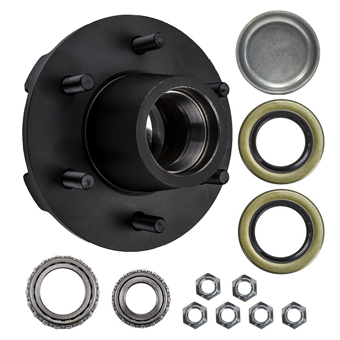
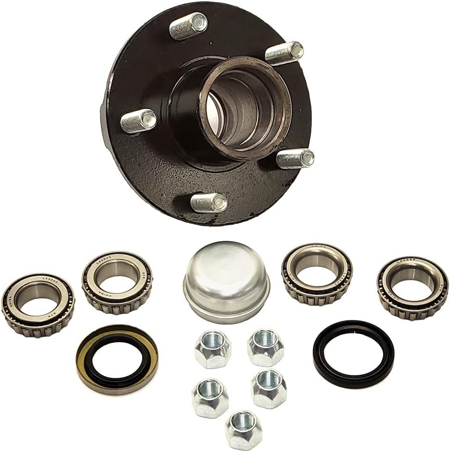
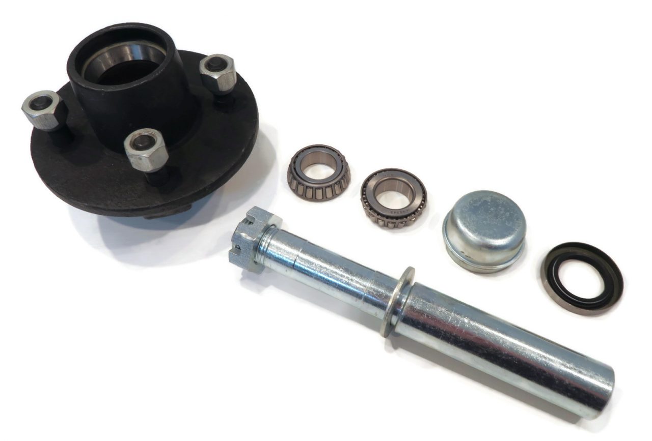
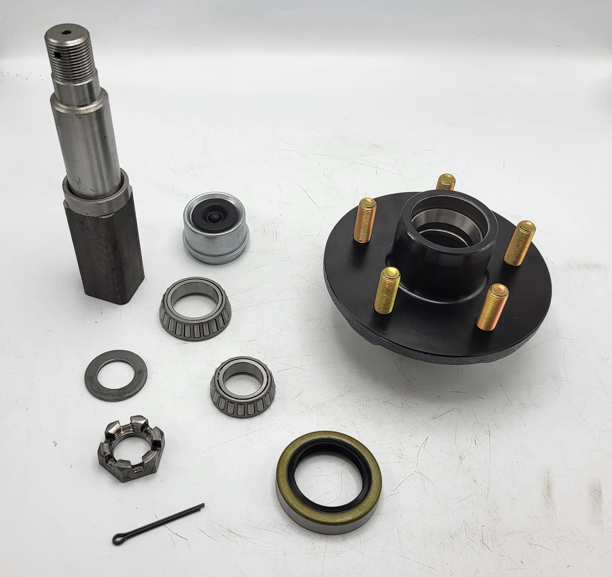
The 5 components of an axle, their function and installationIf you’re considering replacing an axle in your vehicle, you should first understand what it is. It is the component that transmits electricity from 1 part to another. Unlike a fixed steering wheel, the axles are movable. The following article will discuss the 5 components of the half shaft, their function and installation. Hopefully you were able to identify the correct axle for your vehicle. Here are some common problems you may encounter along the way. five componentsThe 5 components of the shaft are flange, bearing surface, spline teeth, spline pitch and pressure angle. The higher the number of splines, the stronger the shaft. The maximum stress that the shaft can withstand increases with the number of spline teeth and spline pitch. The diameter of the shaft times the cube of the pressure angle and spline pitch determines the maximum stress the shaft can withstand. For extreme load applications, use axles made from SAE 4340 and SAE 1550 materials. In addition to these 2 criteria, spline rolling produces a finer grain structure in the material. Cutting the splines reduces the strength of the shaft by 30% and increases stress. FunctionAxles play several important roles in a vehicle. It transfers power from the transmission to the rear differential gearbox and the wheels. The shaft is usually made of steel with cardan joints at both ends. Shaft Shafts can be stationary or rotating. They are all creatures that can transmit electricity and loads. Here are some of their functions. Read on to learn more about axles. Some of their most important features are listed below. MaterialThe material used to make the axle depends on the purpose of the vehicle. For example, overload shafts are usually made of SAE 4340 or 1550 steel. These steels are high strength low alloy alloys that are resistant to bending and buckling. Chromium alloys, for example, are made from steel and have chromium and molybdenum added to increase their toughness and durability. InstallThe process of installing a new shaft is simple. Just loosen the axle nut and remove the set bolt. You may need to tap a few times to get a good seal. After installation, check the shaft at the points marked “A” and “D” to make sure it is in the correct position. Then, press the “F” points on the shaft flange until the points are within 0.002″ of the runout.
China manufacturer High Quality Auto Bearing Rear Wheel Hub for CZPT Tacoma 42450-04010 Wheel Hub Assembly with Hot selling
Product Description
Product Description
Company Profile
ZheJiang Mighty Machinery Co. Ltd is a professional manufacturer of auto bearings for more than 20 years. We provide a one-stop service for our customers. Our main products include wheel bearings & hub assembly, belt tensioners, clutch release bearings, and other parts. Relying on the professional and rich manufacturing experience and many substantial factories which stable cooperated for many years, Mighty suppliers customers high-quality products at very competitive prices.
Customer’s satisfaction is our First Priority, We adhere to the concept of ” Quality First, Customer First”. We will continue to provide high-quality products and the best services to our customers and build up CZPT long-time friendship partners.
Our Advantages More than 20 years of manufacturing and exporting experience Packaging & Shipping FAQ 1. What’s the minimum order quantity? We don’t have the minimum order quantity. We can also provide free samples, but you need to pay the freight. Yes, we provide ODM&OEM services to customers around the world, and we can customize different brands and different sizes of packaging boxes according to customers’ requirements. We guarantee that our products will be free from defects in materials and workmanship within 12 months from the date of delivery. The warranty is void due to improper use, incorrect installation, and physical damage. 4. How to place an order? Send us an email of the models, brand, quantity, consignee information, model of transportation, and payment 5. What are your packing conditions? We use standardized export packaging and environmental protection packaging materials. If you have a legally registered patent, we will package the goods in your brand box after receiving your authorization 6. What are your payment terms? T/T is 30% of the payment in advance and 70% balance before delivery. Before you pay the balance, we will show you photos or videos of the products and packaging. 7. How long is your delivery time? The delivery time of sample order is 3-5 days, and that of a batch order is 5-45 days. The exact delivery time depends on the item and the quantity you ordered. 8. Do you test all products before delivery?
How to Calculate Stiffness, Centering Force, Wear and Fatigue Failure of Spline CouplingsThere are various types of spline couplings. These couplings have several important properties. These properties are: Stiffness, Involute splines, Misalignment, Wear and fatigue failure. To understand how these characteristics relate to spline couplings, read this article. It will give you the necessary knowledge to determine which type of coupling best suits your needs. Keeping in mind that spline couplings are usually spherical in shape, they are made of steel. Involute splinesAn effective side interference condition minimizes gear misalignment. When 2 splines are coupled with no spline misalignment, the maximum tensile root stress shifts to the left by 5 mm. A linear lead variation, which results from multiple connections along the length of the spline contact, increases the effective clearance or interference by a given percentage. This type of misalignment is undesirable for coupling high-speed equipment. Stiffness of couplingThe calculation of stiffness of a spline coupling involves the measurement of its tooth engagement. In the following, we analyze the stiffness of a spline coupling with various types of teeth using 2 different methods. Direct inversion and blockwise inversion both reduce CPU time for stiffness calculation. However, they require evaluation submatrices. Here, we discuss the differences between these 2 methods. MisalignmentTo determine the centering force, the effective pressure angle must be known. Using the effective pressure angle, the centering force is calculated based on the maximum axial and radial loads and updated Dudley misalignment factors. The centering force is the maximum axial force that can be transmitted by friction. Several published misalignment factors are also included in the calculation. A new method is presented in this paper that considers the cam effect in the normal force. Wear and fatigue failureThe failure of a spline coupling due to wear and fatigue is determined by the first occurrence of tooth wear and shaft misalignment. Standard design methods do not account for wear damage and assess the fatigue life with big approximations. Experimental investigations have been conducted to assess wear and fatigue damage in spline couplings. The tests were conducted on a dedicated test rig and special device connected to a standard fatigue machine. The working parameters such as torque, misalignment angle, and axial distance have been varied in order to measure fatigue damage. Over dimensioning has also been assessed.
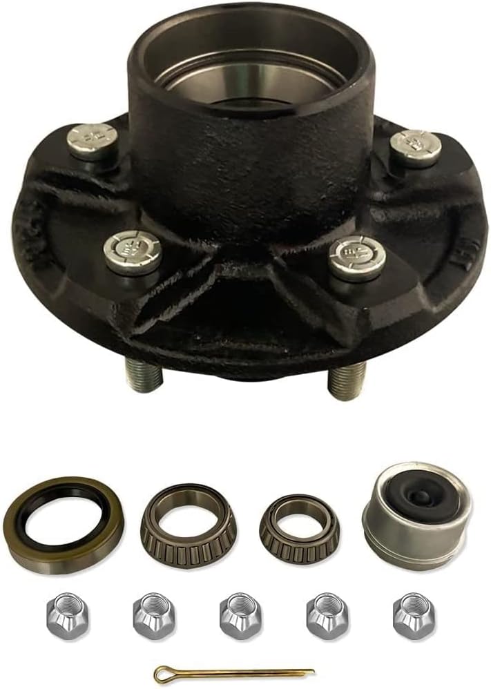
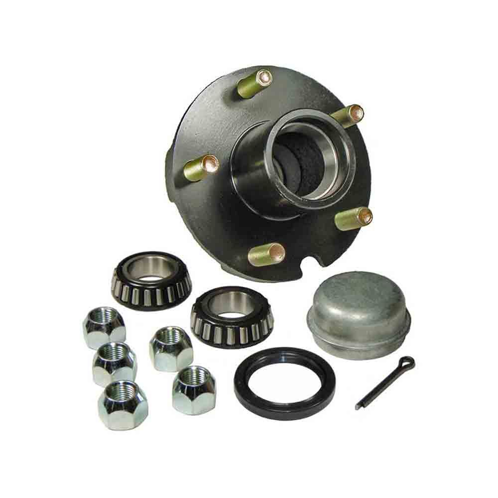
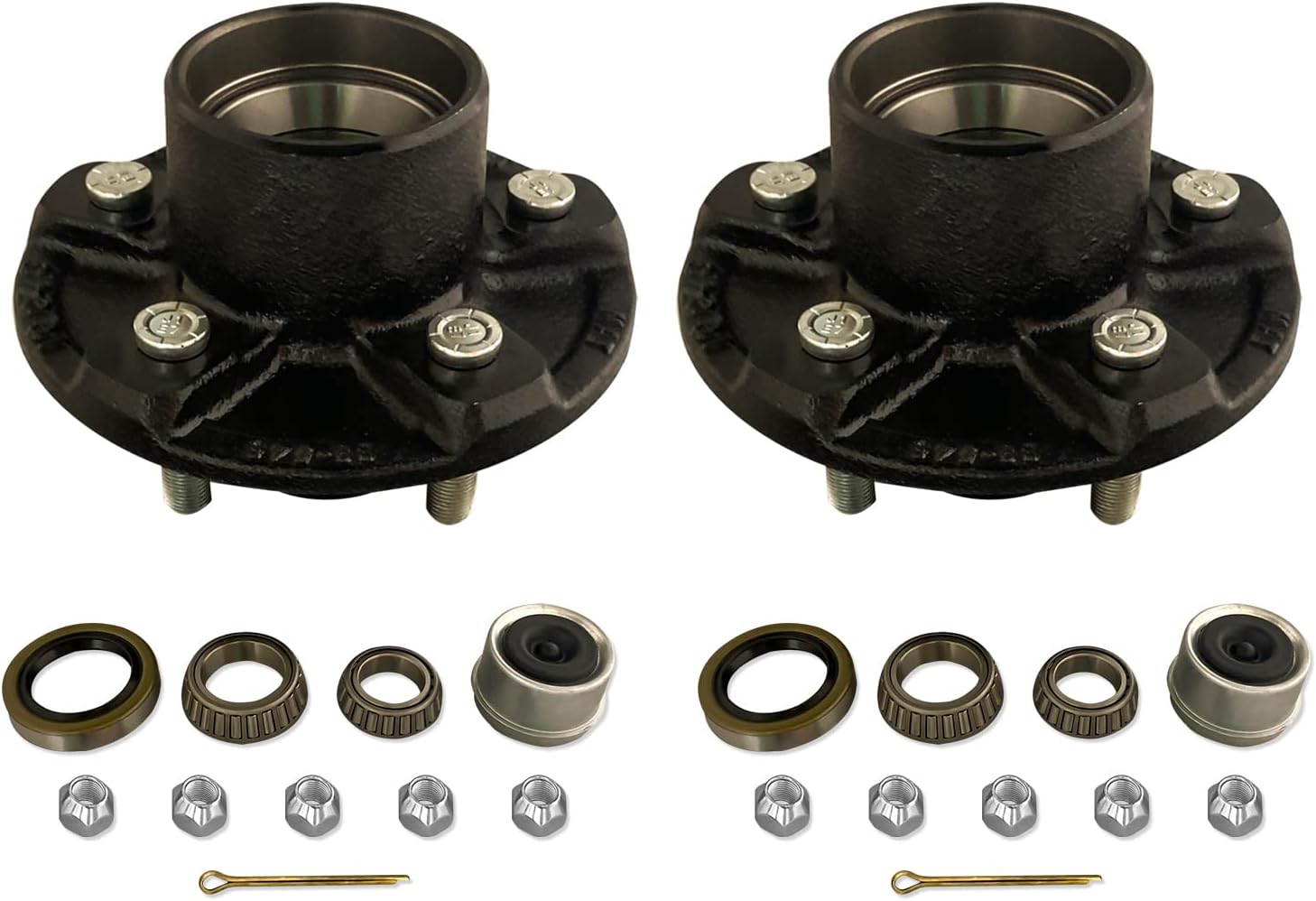
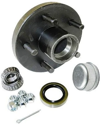
China OEM Auto Parts Wheel Hub Bearing Front Axle Assembly Kit 31206872888 31204081309 31206775771 with Good quality
Product Description
Auto parts wheel hub bearing front axle assembly kit 3120687
MORE PRODUCT
ABOUT US Our main business is ignition coil, spark plugs, auto sensors, air filter, fuel filter, Brake pad, VVT valve ,EGR valve , Steering rack and so on. we had 5 years of experience in this area. We can provide more than 2,000 kinds of products for various brands of vehicles. We are looking forward to trading with overseas customers on the basis of equality and mutual benefit and CZPT benefit cooperation partnership. Certifications
FAQ
|


| OEM | 42200-STX-A02 |
| Brand | FENGMING |
| Condition | Brand New |
| Stock Availability | Yes |
| Minimum Order QTY | 2PC |
| OEM Order Acceptability | Yes |
| Small order Lead Time | 3-7 days |
| Large Order Lead Time | 15-30 days |
| Quality Warranty | 12 Months |
| Package | As netural or as customer’s request, FENG MING PACKING |
| Payment Methods | Paypal, Western Union, Bank T/T, L/C |
| Shipment Methods | DHL, UPS, TNT, FedEx, Aramex, EMS, Air Cargo, Sea Cargo |
Company Profile
Analytical Approaches to Estimating Contact Pressures in Spline Couplings
A spline coupling is a type of mechanical connection between 2 rotating shafts. It consists of 2 parts – a coupler and a coupling. Both parts have teeth which engage and transfer loads. However, spline couplings are typically over-dimensioned, which makes them susceptible to fatigue and static behavior. Wear phenomena can also cause the coupling to fail. For this reason, proper spline coupling design is essential for achieving optimum performance.
Modeling a spline coupling
Spline couplings are becoming increasingly popular in the aerospace industry, but they operate in a slightly misaligned state, causing both vibrations and damage to the contact surfaces. To solve this problem, this article offers analytical approaches for estimating the contact pressures in a spline coupling. Specifically, this article compares analytical approaches with pure numerical approaches to demonstrate the benefits of an analytical approach.
To model a spline coupling, first you create the knowledge base for the spline coupling. The knowledge base includes a large number of possible specification values, which are related to each other. If you modify 1 specification, it may lead to a warning for violating another. To make the design valid, you must create a spline coupling model that meets the specified specification values.
After you have modeled the geometry, you must enter the contact pressures of the 2 spline couplings. Then, you need to determine the position of the pitch circle of the spline. In Figure 2, the centre of the male coupling is superposed to that of the female spline. Then, you need to make sure that the alignment meshing distance of the 2 splines is the same.
Once you have the data you need to create a spline coupling model, you can begin by entering the specifications for the interface design. Once you have this data, you need to choose whether to optimize the internal spline or the external spline. You’ll also need to specify the tooth friction coefficient, which is used to determine the stresses in the spline coupling model 20. You should also enter the pilot clearance, which is the clearance between the tip 186 of a tooth 32 on 1 spline and the feature on the mating spline.
After you have entered the desired specifications for the external spline, you can enter the parameters for the internal spline. For example, you can enter the outer diameter limit 154 of the major snap 54 and the minor snap 56 of the internal spline. The values of these parameters are displayed in color-coded boxes on the Spline Inputs and Configuration GUI screen 80. Once the parameters are entered, you’ll be presented with a geometric representation of the spline coupling model 20.
Creating a spline coupling model 20
The spline coupling model 20 is created by a product model software program 10. The software validates the spline coupling model against a knowledge base of configuration-dependent specification constraints and relationships. This report is then input to the ANSYS stress analyzer program. It lists the spline coupling model 20’s geometric configurations and specification values for each feature. The spline coupling model 20 is automatically recreated every time the configuration or performance specifications of the spline coupling model 20 are modified.
The spline coupling model 20 can be configured using the product model software program 10. A user specifies the axial length of the spline stack, which may be zero, or a fixed length. The user also enters a radial mating face 148, if any, and selects a pilot clearance specification value of 14.5 degrees or 30 degrees.
A user can then use the mouse 110 to modify the spline coupling model 20. The spline coupling knowledge base contains a large number of possible specification values and the spline coupling design rule. If the user tries to change a spline coupling model, the model will show a warning about a violation of another specification. In some cases, the modification may invalidate the design.
In the spline coupling model 20, the user enters additional performance requirement specifications. The user chooses the locations where maximum torque is transferred for the internal and external splines 38 and 40. The maximum torque transfer location is determined by the attachment configuration of the hardware to the shafts. Once this is selected, the user can click “Next” to save the model. A preview of the spline coupling model 20 is displayed.
The model 20 is a representation of a spline coupling. The spline specifications are entered in the order and arrangement as specified on the spline coupling model 20 GUI screen. Once the spline coupling specifications are entered, the product model software program 10 will incorporate them into the spline coupling model 20. This is the last step in spline coupling model creation.
Analysing a spline coupling model 20
An analysis of a spline coupling model consists of inputting its configuration and performance specifications. These specifications may be generated from another computer program. The product model software program 10 then uses its internal knowledge base of configuration dependent specification relationships and constraints to create a valid three-dimensional parametric model 20. This model contains information describing the number and types of spline teeth 32, snaps 34, and shoulder 36.
When you are analysing a spline coupling, the software program 10 will include default values for various specifications. The spline coupling model 20 comprises an internal spline 38 and an external spline 40. Each of the splines includes its own set of parameters, such as its depth, width, length, and radii. The external spline 40 will also contain its own set of parameters, such as its orientation.
Upon selecting these parameters, the software program will perform various analyses on the spline coupling model 20. The software program 10 calculates the nominal and maximal tooth bearing stresses and fatigue life of a spline coupling. It will also determine the difference in torsional windup between an internal and an external spline. The output file from the analysis will be a report file containing model configuration and specification data. The output file may also be used by other computer programs for further analysis.
Once these parameters are set, the user enters the design criteria for the spline coupling model 20. In this step, the user specifies the locations of maximum torque transfer for both the external and internal spline 38. The maximum torque transfer location depends on the configuration of the hardware attached to the shafts. The user may enter up to 4 different performance requirement specifications for each spline.
The results of the analysis show that there are 2 phases of spline coupling. The first phase shows a large increase in stress and vibration. The second phase shows a decline in both stress and vibration levels. The third stage shows a constant meshing force between 300N and 320N. This behavior continues for a longer period of time, until the final stage engages with the surface.
Misalignment of a spline coupling
A study aimed to investigate the position of the resultant contact force in a spline coupling engaging teeth under a steady torque and rotating misalignment. The study used numerical methods based on Finite Element Method (FEM) models. It produced numerical results for nominal conditions and parallel offset misalignment. The study considered 2 levels of misalignment – 0.02 mm and 0.08 mm – with different loading levels.
The results showed that the misalignment between the splines and rotors causes a change in the meshing force of the spline-rotor coupling system. Its dynamics is governed by the meshing force of splines. The meshing force of a misaligned spline coupling is related to the rotor-spline coupling system parameters, the transmitting torque, and the dynamic vibration displacement.
Despite the lack of precise measurements, the misalignment of splines is a common problem. This problem is compounded by the fact that splines usually feature backlash. This backlash is the result of the misaligned spline. The authors analyzed several splines, varying pitch diameters, and length/diameter ratios.
A spline coupling is a two-dimensional mechanical system, which has positive backlash. The spline coupling is comprised of a hub and shaft, and has tip-to-root clearances that are larger than the backlash. A form-clearance is sufficient to prevent tip-to-root fillet contact. The torque on the splines is transmitted via friction.
When a spline coupling is misaligned, a torque-biased thrust force is generated. In such a situation, the force can exceed the torque, causing the component to lose its alignment. The two-way transmission of torque and thrust is modeled analytically in the present study. The analytical approach provides solutions that can be integrated into the design process. So, the next time you are faced with a misaligned spline coupling problem, make sure to use an analytical approach!
In this study, the spline coupling is analyzed under nominal conditions without a parallel offset misalignment. The stiffness values obtained are the percentage difference between the nominal pitch diameter and load application diameter. Moreover, the maximum percentage difference in the measured pitch diameter is 1.60% under a torque of 5000 N*m. The other parameter, the pitch angle, is taken into consideration in the calculation.
China OEM Rear Axle Left and Right Side Wheel Bearing Kit Auto Parts 3748.88 713640460 Vkba6500 R159.50 Fit for Citroen Berlingo and P-Eugeot Partner near me shop
Product Description
Basic information:Pictures:
| Name | wheel hub bearings 3748.88 |
| Material | steel GCr15, 65Mn, or 55 |
| Application car makes | CITROEN/P-EUGEOT: |
| Size | ID: 32mm OD: 129 mm Height: 61 mm |
| Holes | 4 Holes |
| Weight | 0.38 kg |
| Brand | SI, PPB, or customized |
| Packing | Neutral, our brand packing or customized |
| OEM replacement | Yes |
| Manufacture place | ZHangZhoug, China |
| MOQ | 100 PCS |
| Warranty | 1 year or 40,000-50,000 KMS |
| Certificate | ISO9001:2015 |
| Payment | T/T, PayPal, Alibaba |
OEM:
CITROEN/P-EUGEOT: 3748.88
Other Ref.:
F-AG :
FEBI BILSTEIN : 47833
GSP : 9232571
GSP : 9232571K
MOOG : PE-WB-11407
OPTIMAL : 657146
S-KF : VKBA6500
SNR : R159.50
Application:
CITROEN BERLINGO / BERLINGO FIRST Box 1996-2011
CITROEN XSARA PICASSO 1999-2011
P-EUGEOT PARTNER 1996-2015
Other types(contact us for more models):
| S-KF VKBA Code | Application |
| VKBA 6896 | S-UBARU |
| VKBA 6897 | S-UBARU |
| VKBA 6898 | TOYOTA |
| VKBA 6900 | TOYOTA |
| VKBA 6901 | TOYOTA |
| VKBA 6905 | HYUNDAI,KIA |
| VKBA 6906 | L EXUS,TOYOTA |
| VKBA 6907 | L EXUS,TOYOTA |
| VKBA 6908 | TOYOTA |
| VKBA 6909 | L EXUS,TOYOTA |
| VKBA 6910 | TOYOTA |
| VKBA 6913 | MITSUBISHI |
| VKBA 6914 | MITSUBISHI |
| VKBA 6915 | MITSUBISHI |
| VKBA 6917 | HONDA |
| VKBA 6920 | DAIHATSU,TOYOTA |
| VKBA 6921 | DAIHATSU |
| VKBA 6923 | HYUNDAI,KIA |
| VKBA 6924 | TOYOTA |
| VKBA 6926 | MITSUBISHI |
| VKBA 6927 | MITSUBISHI |
| VKBA 6928 | MITSUBISHI |
| VKBA 6931 | HYUNDAI,KIA |
| VKBA 6938 | HYUNDAI |
| VKBA 6939 | HYUNDAI |
| VKBA 6940 | HYUNDAI |
| VKBA 6941 | HYUNDAI |
| VKBA 6942 | HYUNDAI |
| VKBA 6943 | HYUNDAI,KIA |
| VKBA 6944 | KIA |
| VKBA 6948 | HYUNDAI,KIA |
| VKBA 6949 | HYUNDAI |
| VKBA 6950 | HYUNDAI,KIA |
| VKBA 6953 | L EXUS |
| VKBA 6954 | L EXUS |
| VKBA 6955 | L EXUS |
| VKBA 6956 | HYUNDAI,KIA,TOYOTA |
| VKBA 6959 | L EXUS |
| VKBA 6961 | L EXUS |
| VKBA 6963 | L EXUS,TOYOTA |
| VKBA 6964 | MITSUBISHI |
| VKBA 6966 | DAIHATSU |
| VKBA 6967 | DAIHATSU |
| VKBA 6968 | DAIHATSU |
| VKBA 6972 | MAZDA |
| VKBA 6975 | SUZUKI |
| VKBA 6976 | SUZUKI |
| VKBA 6978 | SUZUKI |
| VKBA 6979 | SUZUKI |
| VKBA 6980 | SUZUKI |
| VKBA 6981 | NISSAN |
| VKBA 6984 | NISSAN |
| VKBA 6985 | NISSAN |
| VKBA 6990 | CHEVROLET |
| VKBA 6991 | HONDA |
| VKBA 6996 | NISSAN,R-ENAULT |
| VKBA 6997 | NISSAN,R-ENAULT |
| VKBA 6998 | NISSAN,R-ENAULT |
| VKBA 6999 | NISSAN |
| VKBA 713 | MITSUBISHI |
| VKBA 715 | MITSUBISHI |
| VKBA 717 | MAZDA |
| VKBA 719 | V-OLVO |
| VKBA 725 | ALFA ROMEO |
| VKBA 727 | AUSTIN |
| VKBA 728 | CITROËN,P-EUGEOT,TALBOT |
| VKBA 730 | AUSTIN,ROVER |
| VKBA 732 | V-OLVO |
| VKBA 733 | V-OLVO |
| VKBA 734 | FIAT,LXIHU (WEST LAKE) DIS.A,SEAT |
| VKBA 736 | O-PEL,VAUXHALL |
| VKBA 739 | MAZDA |
| VKBA 740 | FORD |
| VKBA 7400 | CHEVROLET,DAEWOO |
| VKBA 7401 | CHEVROLET,DAEWOO |
| VKBA 7403 | NISSAN |
| VKBA 7405 | MITSUBISHI |
| VKBA 7406 | MITSUBISHI |
| VKBA 7407 | MITSUBISHI |
| VKBA 7408 | CITROËN,DODGE,MITSUBISHI, P-EUGEOT |
| VKBA 7409 | CITROËN,MITSUBISHI,P-EUGEOT |
| VKBA 741 | FORD |
| VKBA 7410 | MITSUBISHI |
| VKBA 7412 | MITSUBISHI |
| VKBA 7413 | MITSUBISHI |
| VKBA 7414 | HYUNDAI,KIA |
| VKBA 7417 | MITSUBISHI |
| VKBA 7418 | NISSAN |
| VKBA 7419 | CHEVROLET,DAEWOO |
| VKBA 7427 | TOYOTA |
| VKBA 743 | CITROËN,P-EUGEOT |
| VKBA 7430 | TOYOTA |
| VKBA 7435 | MITSUBISHI |
| VKBA 7437 | CHEVROLET,O-PEL,VAUXHALL |
| VKBA 7439 | CHEVROLET,O-PEL,VAUXHALL |
| VKBA 7440 | HONDA |
| VKBA 7441 | HONDA |
| VKBA 7446 | MAZDA |
| VKBA 7447 | HONDA |
| VKBA 7449 | MAZDA |
| VKBA 745 | SAAB |
| VKBA 7451 | MITSUBISHI |
| VKBA 7454 | HYUNDAI |
| VKBA 7455 | SUZUKI |
| VKBA 7456 | SUZUKI |
| VKBA 7458 | SUZUKI |
| VKBA 7459 | SUZUKI |
| VKBA 7460 | SUZUKI |
| VKBA 7461 | HYUNDAI |
| VKBA 7462 | TOYOTA |
| VKBA 7468 | MAZDA |
| VKBA 7469 | HONDA |
| VKBA 7470 | I SUZU |
| VKBA 7472 | I SUZU |
| VKBA 7474 | NISSAN |
| VKBA 7478 | I SUZU |
| VKBA 7479 | S-UBARU |
| VKBA 7482 | KIA |
| VKBA 7488 | KIA |
| VKBA 7489 | KIA |
| VKBA 749 | AUSTIN,ROVER |
| VKBA 7490 | HONDA |
| VKBA 7491 | HONDA |
| VKBA 7492 | CHEVROLET,O-PEL,VAUXHALL |
| VKBA 7493 | CHEVROLET,O-PEL,VAUXHALL |
| VKBA 7497 | TOYOTA |
| VKBA 7498 | NISSAN |
| VKBA 7505 | CITROËN,MITSUBISHI,P-EUGEOT |
| VKBA 751 | NISSAN |
| VKBA 752 | ALFA ROMEO,NISSAN |
| VKBA 7525 | SUZUKI |
| VKBA 7526 | O-PEL,SUZUKI,VAUXHALL |
| VKBA 7529 | TOYOTA |
| VKBA 753 | MAZDA |
| VKBA 7534 | MAZDA |
| VKBA 7536 | MAZDA |
| VKBA 7537 | MAZDA |
| VKBA 7538 | MAZDA |
| VKBA 754 | O-PEL,VAUXHALL |
| VKBA 7540 | HONDA |
Other Parts:
Wheel Bearings, wheel hub bearings, wheel hub assembly, Wheel Bearing Hub, Wheel Hubs, Wheel Bearing And Hub Assembly, Wheel Bearing Hub Assembly Front, Wheel Bearing Hub Assembly, Wheel Bearing & Hub Assembly, Right Front Hub Bearing Assembly, Abs Hub Bearing Assembly, Hub And Bearing Assembly Front, Left Front Hub Bearing Assembly, Hub Bearing Assembly, hub and bearing replacement, hub bearing assembly front, bearing assembly, Front Wheel Bearing and Hub Assembly, Front Wheel Drive Hub and Bearing Assembly, Front Axle Bearing & Hub Assembly, Front Bearing Hub Assembly, Front Wheel Hub And Bearing Assembly, Front Wheel Bearing Hub Assembly Replacement, front bearing hub replacement, front wheel bearing hub assembly, front wheel bearing hub replacement, rear wheel bearing, rear wheel hub, rear hub assembly, hub bearing assembly rear, rear axle bearing and hubs
SI&PPB bearing has a plant area of 50,000 square meters, assets of RMB180 million, 500 employees, and 150 professional and technical personnel. The company uses high-quality GCR15 as its raw materials and uses Austenite heat treatment to ensure the service life of the products.
“The factory produces series models of mechanical clutch release bearings, belt tension wheel units, wheel bearings, and wheel bearing repair kits.
Partial products are produced by professional outsourcing factories, and the company’s testing center provides professional testing to ensure that the products meet the drawings or customer’s requirements.”
Packing:
FAQ:
Q1.What is your shipping logistic?
Re: DHL, TNT, FedEx express, by air/sea/train.
Q2:What’s the MOQ?
Re: For the wheel hub bearing repair kit. The MOQ is always 50 sets. If ordering together with other models, small quantities can be organized. But need more time due to the production schedule.
Q3. What are your goods of packing?
Re: Generally, our goods will be packed in Neutral white or brown boxes for the hub bearing unit. Our brand packing SI & CZPT are offered. If you have any other packing requests, we shall also handle them.
Q4. What is your sample policy?
Re: We can supply the sample if we have ready parts in stock.
Q5. Do you have any certificates?
Re: Yes, we have the certificate of ISO9001:2015.
Q6:Any warranty of your products.
Re: Sure, We are offering a guaranty for 12 months or 40,000-50,000 km for the aftermarket.
Driveshaft structure and vibrations associated with it
The structure of the drive shaft is critical to its efficiency and reliability. Drive shafts typically contain claw couplings, rag joints and universal joints. Other drive shafts have prismatic or splined joints. Learn about the different types of drive shafts and how they work. If you want to know the vibrations associated with them, read on. But first, let’s define what a driveshaft is.
transmission shaft
As the demand on our vehicles continues to increase, so does the demand on our drive systems. Higher CO2 emission standards and stricter emission standards increase the stress on the drive system while improving comfort and shortening the turning radius. These and other negative effects can place significant stress and wear on components, which can lead to driveshaft failure and increase vehicle safety risks. Therefore, the drive shaft must be inspected and replaced regularly.
Depending on your model, you may only need to replace 1 driveshaft. However, the cost to replace both driveshafts ranges from $650 to $1850. Additionally, you may incur labor costs ranging from $140 to $250. The labor price will depend on your car model and its drivetrain type. In general, however, the cost of replacing a driveshaft ranges from $470 to $1850.
Regionally, the automotive driveshaft market can be divided into 4 major markets: North America, Europe, Asia Pacific, and Rest of the World. North America is expected to dominate the market, while Europe and Asia Pacific are expected to grow the fastest. Furthermore, the market is expected to grow at the highest rate in the future, driven by economic growth in the Asia Pacific region. Furthermore, most of the vehicles sold globally are produced in these regions.
The most important feature of the driveshaft is to transfer the power of the engine to useful work. Drive shafts are also known as propeller shafts and cardan shafts. In a vehicle, a propshaft transfers torque from the engine, transmission, and differential to the front or rear wheels, or both. Due to the complexity of driveshaft assemblies, they are critical to vehicle safety. In addition to transmitting torque from the engine, they must also compensate for deflection, angular changes and length changes.
type
Different types of drive shafts include helical shafts, gear shafts, worm shafts, planetary shafts and synchronous shafts. Radial protruding pins on the head provide a rotationally secure connection. At least 1 bearing has a groove extending along its circumferential length that allows the pin to pass through the bearing. There can also be 2 flanges on each end of the shaft. Depending on the application, the shaft can be installed in the most convenient location to function.
Propeller shafts are usually made of high-quality steel with high specific strength and modulus. However, they can also be made from advanced composite materials such as carbon fiber, Kevlar and fiberglass. Another type of propeller shaft is made of thermoplastic polyamide, which is stiff and has a high strength-to-weight ratio. Both drive shafts and screw shafts are used to drive cars, ships and motorcycles.
Sliding and tubular yokes are common components of drive shafts. By design, their angles must be equal or intersect to provide the correct angle of operation. Unless the working angles are equal, the shaft vibrates twice per revolution, causing torsional vibrations. The best way to avoid this is to make sure the 2 yokes are properly aligned. Crucially, these components have the same working angle to ensure smooth power flow.
The type of drive shaft varies according to the type of motor. Some are geared, while others are non-geared. In some cases, the drive shaft is fixed and the motor can rotate and steer. Alternatively, a flexible shaft can be used to control the speed and direction of the drive. In some applications where linear power transmission is not possible, flexible shafts are a useful option. For example, flexible shafts can be used in portable devices.
put up
The construction of the drive shaft has many advantages over bare metal. A shaft that is flexible in multiple directions is easier to maintain than a shaft that is rigid in other directions. The shaft body and coupling flange can be made of different materials, and the flange can be made of a different material than the main shaft body. For example, the coupling flange can be made of steel. The main shaft body is preferably flared on at least 1 end, and the at least 1 coupling flange includes a first generally frustoconical projection extending into the flared end of the main shaft body.
The normal stiffness of fiber-based shafts is achieved by the orientation of parallel fibers along the length of the shaft. However, the bending stiffness of this shaft is reduced due to the change in fiber orientation. Since the fibers continue to travel in the same direction from the first end to the second end, the reinforcement that increases the torsional stiffness of the shaft is not affected. In contrast, a fiber-based shaft is also flexible because it uses ribs that are approximately 90 degrees from the centerline of the shaft.
In addition to the helical ribs, the drive shaft 100 may also contain reinforcing elements. These reinforcing elements maintain the structural integrity of the shaft. These reinforcing elements are called helical ribs. They have ribs on both the outer and inner surfaces. This is to prevent shaft breakage. These elements can also be shaped to be flexible enough to accommodate some of the forces generated by the drive. Shafts can be designed using these methods and made into worm-like drive shafts.
vibration
The most common cause of drive shaft vibration is improper installation. There are 5 common types of driveshaft vibration, each related to installation parameters. To prevent this from happening, you should understand what causes these vibrations and how to fix them. The most common types of vibration are listed below. This article describes some common drive shaft vibration solutions. It may also be beneficial to consider the advice of a professional vibration technician for drive shaft vibration control.
If you’re not sure if the problem is the driveshaft or the engine, try turning on the stereo. Thicker carpet kits can also mask vibrations. Nonetheless, you should contact an expert as soon as possible. If vibration persists after vibration-related repairs, the driveshaft needs to be replaced. If the driveshaft is still under warranty, you can repair it yourself.
CV joints are the most common cause of third-order driveshaft vibration. If they are binding or fail, they need to be replaced. Alternatively, your CV joints may just be misaligned. If it is loose, you can check the CV connector. Another common cause of drive shaft vibration is improper assembly. Improper alignment of the yokes on both ends of the shaft can cause them to vibrate.
Incorrect trim height can also cause driveshaft vibration. Correct trim height is necessary to prevent drive shaft wobble. Whether your vehicle is new or old, you can perform some basic fixes to minimize problems. One of these solutions involves balancing the drive shaft. First, use the hose clamps to attach the weights to it. Next, attach an ounce of weight to it and spin it. By doing this, you minimize the frequency of vibration.
cost
The global driveshaft market is expected to exceed (xxx) million USD by 2028, growing at a compound annual growth rate (CAGR) of XX%. Its soaring growth can be attributed to several factors, including increasing urbanization and R&D investments by leading market players. The report also includes an in-depth analysis of key market trends and their impact on the industry. Additionally, the report provides a comprehensive regional analysis of the Driveshaft Market.
The cost of replacing the drive shaft depends on the type of repair required and the cause of the failure. Typical repair costs range from $300 to $750. Rear-wheel drive cars usually cost more. But front-wheel drive vehicles cost less than four-wheel drive vehicles. You may also choose to try repairing the driveshaft yourself. However, it is important to do your research and make sure you have the necessary tools and equipment to perform the job properly.
The report also covers the competitive landscape of the Drive Shafts market. It includes graphical representations, detailed statistics, management policies, and governance components. Additionally, it includes a detailed cost analysis. Additionally, the report presents views on the COVID-19 market and future trends. The report also provides valuable information to help you decide how to compete in your industry. When you buy a report like this, you are adding credibility to your work.
A quality driveshaft can improve your game by ensuring distance from the tee and improving responsiveness. The new material in the shaft construction is lighter, stronger and more responsive than ever before, so it is becoming a key part of the driver. And there are a variety of options to suit any budget. The main factor to consider when buying a shaft is its quality. However, it’s important to note that quality doesn’t come cheap and you should always choose an axle based on what your budget can handle.
China Professional Axle Front Wheel Bearing Hub Japan Auto Rear Wheel Hub Bearing for CZPT Vitsz Hiace Altis CZPT Grandis L200 CZPT Hyundai Nissan Honda near me manufacturer
Product Description
HOT Sale Automotive Front Wheel Hub Bearing Assembly for Japan Car (45712-CG110) (45712-EJ70B) For Infiniti FX35-FX45
| Part Name | Shock Absorber |
| Brand | KINGSTEEL/JECICO |
| Application | Auto Suspension System |
| car maker | for CZPT Vitsz Hiace Altis CZPT Grandis L2 48530-20820 |
| Placement on Vehicle | Suspension System |
| Material | Aluminum/iron/Steel |
| Warranty | 12 Months |
| Sample | Available |
| Price | $20-$25 |
| Place of origin | HangZhou |
| Delivery time | 1-7 days for stock items, 65 days for produced items |
| Packing | KINGSTEEL/JECICO/CUSTOMER DEMAND |
| CTN/QTY | 4-10 PCS |
| Payment | L/C,T/T,Western Union,PayPal |
FAQ
1.Are you trading company or factory?
We are invested factory with trading company.
2.What products does your company supply for CZPT brand?
1) Control arm and ball joint tie rod end, rack end, linkage.
2) Drive shaft, cv joint, and tripod joints
3) Wheel hub, wheel bearing
4) Brake pads, brake shoes, brake caliper ,brake disc
5) Steering rack, steering pump, steering knuckle
6) Shock absorber
7) Engine mount
8) Clutch plate, clutch cover
9) Ignition coil, clock spring ,
10) fuel pump, oil filter, fan belt timing, belt tensioner pully
3.What is the MOQ for each items?
If the items we have stock, there is no limitation for moq, and narmally MOQ as 10pcs is acceptable.
4.Do you give any guarantee to your products?
Yes, we have 1years quality guarantee. Only brake pad, brake shoe, fan belt timing belt is gurantee 30000KM.
5.How does to control your CZPT products ?
1.There is advanced equipment,professional and technical workersin the factory.
2.Factory will have sample testing on quality before shipment.
3.Our QC(QUALITY CONTROL) will check the quality of each productbefore shipment
6. How long for delivery time after pay deposit?
-Usually 20-35 days for production.
Some hot sales items have stock.
7. Which countries have you exported for CZPT brand ?
ASIA:Iraq, Lebanon, UAE, Turkey, Malaysia, Vietnam, LAOS, Thailand, Syria, Saudi Arabia, Kazakhstan, Turkmenistan, Azerbaijan.
EUROPE:Russia, lreland, Uk, Poland, Greece.
OCEANIA: Australia, Fiji,Kiribati, New Zealand.
SOUTH AMERICA:Panama, Xihu (West Lake) Dis.via, Peru, Chile, Paraguay, Guatemala, Barbados
NORTH AMERICA : United States, Canada, Mexic, Yamaica
AFRICA:Nigeria, Angola, Ghana, Egypt, Uganda, Burkina faso, Libya , Mozambique
8.What service can you provide if we buy your brand products?
1. you can get gifts according to point redemption you have, like U-disk, watches, clothes, cups, etc.
2.Recommend same market customers to buy from you.
9.What will you do for quality complaint ?
1.We will respond to customer within 24 hours.
2.Our QC will retest the same stock item, if confirmed it is quality problem, we will make corresponding compensation.
Screw Shaft Features Explained
When choosing the screw shaft for your application, you should consider the features of the screws: threads, lead, pitch, helix angle, and more. You may be wondering what these features mean and how they affect the screw’s performance. This article explains the differences between these factors. The following are the features that affect the performance of screws and their properties. You can use these to make an informed decision and purchase the right screw. You can learn more about these features by reading the following articles.
Threads
The major diameter of a screw thread is the larger of the 2 extreme diameters. The major diameter of a screw is also known as the outside diameter. This dimension can’t be directly measured, but can be determined by measuring the distance between adjacent sides of the thread. In addition, the mean area of a screw thread is known as the pitch. The diameter of the thread and pitch line are directly proportional to the overall size of the screw.
The threads are classified by the diameter and pitch. The major diameter of a screw shaft has the largest number of threads; the smaller diameter is called the minor diameter. The thread angle, also known as the helix angle, is measured perpendicular to the axis of the screw. The major diameter is the largest part of the screw; the minor diameter is the lower end of the screw. The thread angle is the half distance between the major and minor diameters. The minor diameter is the outer surface of the screw, while the top surface corresponds to the major diameter.
The pitch is measured at the crest of a thread. In other words, a 16-pitch thread has a diameter of 1 sixteenth of the screw shaft’s diameter. The actual diameter is 0.03125 inches. Moreover, a large number of manufacturers use this measurement to determine the thread pitch. The pitch diameter is a critical factor in successful mating of male and female threads. So, when determining the pitch diameter, you need to check the thread pitch plate of a screw.
Lead
In screw shaft applications, a solid, corrosion-resistant material is an important requirement. Lead screws are a robust choice, which ensure shaft direction accuracy. This material is widely used in lathes and measuring instruments. They have black oxide coatings and are suited for environments where rusting is not acceptable. These screws are also relatively inexpensive. Here are some advantages of lead screws. They are highly durable, cost-effective, and offer high reliability.
A lead screw system may have multiple starts, or threads that run parallel to each other. The lead is the distance the nut travels along the shaft during a single revolution. The smaller the lead, the tighter the thread. The lead can also be expressed as the pitch, which is the distance between adjacent thread crests or troughs. A lead screw has a smaller pitch than a nut, and the smaller the lead, the greater its linear speed.
When choosing lead screws, the critical speed is the maximum number of revolutions per minute. This is determined by the minor diameter of the shaft and its length. The critical speed should never be exceeded or the lead will become distorted or cracked. The recommended operational speed is around 80 percent of the evaluated critical speed. Moreover, the lead screw must be properly aligned to avoid excessive vibrations. In addition, the screw pitch must be within the design tolerance of the shaft.
Pitch
The pitch of a screw shaft can be viewed as the distance between the crest of a thread and the surface where the threads meet. In mathematics, the pitch is equivalent to the length of 1 wavelength. The pitch of a screw shaft also relates to the diameter of the threads. In the following, the pitch of a screw is explained. It is important to note that the pitch of a screw is not a metric measurement. In the following, we will define the 2 terms and discuss how they relate to 1 another.
A screw’s pitch is not the same in all countries. The United Kingdom, Canada, and the United States have standardized screw threads according to the UN system. Therefore, there is a need to specify the pitch of a screw shaft when a screw is being manufactured. The standardization of pitch and diameter has also reduced the cost of screw manufacturing. Nevertheless, screw threads are still expensive. The United Kingdom, Canada, and the United States have introduced a system for the calculation of screw pitch.
The pitch of a lead screw is the same as that of a lead screw. The diameter is 0.25 inches and the circumference is 0.79 inches. When calculating the mechanical advantage of a screw, divide the diameter by its pitch. The larger the pitch, the more threads the screw has, increasing its critical speed and stiffness. The pitch of a screw shaft is also proportional to the number of starts in the shaft.
Helix angle
The helix angle of a screw shaft is the angle formed between the circumference of the cylinder and its helix. Both of these angles must be equal to 90 degrees. The larger the lead angle, the smaller the helix angle. Some reference materials refer to angle B as the helix angle. However, the actual angle is derived from calculating the screw geometry. Read on for more information. Listed below are some of the differences between helix angles and lead angles.
High helix screws have a long lead. This length reduces the number of effective turns of the screw. Because of this, fine pitch screws are usually used for small movements. A typical example is a 16-mm x 5-inch screw. Another example of a fine pitch screw is a 12x2mm screw. It is used for small moves. This type of screw has a lower lead angle than a high-helix screw.
A screw’s helix angle refers to the relative angle of the flight of the helix to the plane of the screw axis. While screw helix angles are not often altered from the standard square pitch, they can have an effect on processing. Changing the helix angle is more common in two-stage screws, special mixing screws, and metering screws. When a screw is designed for this function, it should be able to handle the materials it is made of.
Size
The diameter of a screw is its diameter, measured from the head to the shaft. Screw diameters are standardized by the American Society of Mechanical Engineers. The diameters of screws range from 3/50 inches to 16 inches, and more recently, fractions of an inch have been added. However, shaft diameters may vary depending on the job, so it is important to know the right size for the job. The size chart below shows the common sizes for screws.
Screws are generally referred to by their gauge, which is the major diameter. Screws with a major diameter less than a quarter of an inch are usually labeled as #0 to #14 and larger screws are labeled as sizes in fractions of an inch. There are also decimal equivalents of each screw size. These measurements will help you choose the correct size for your project. The screws with the smaller diameters were not tested.
In the previous section, we described the different shaft sizes and their specifications. These screw sizes are usually indicated by fractions of an inch, followed by a number of threads per inch. For example, a ten-inch screw has a shaft size of 2” with a thread pitch of 1/4″, and it has a diameter of 2 inches. This screw is welded to a two-inch Sch. 40 pipe. Alternatively, it can be welded to a 9-inch O.A.L. pipe.
Shape
Screws come in a wide variety of sizes and shapes, from the size of a quarter to the diameter of a U.S. quarter. Screws’ main function is to hold objects together and to translate torque into linear force. The shape of a screw shaft, if it is round, is the primary characteristic used to define its use. The following chart shows how the screw shaft differs from a quarter:
The shape of a screw shaft is determined by 2 features: its major diameter, or distance from the outer edge of the thread on 1 side to the inner smooth surface of the shaft. These are generally 2 to 16 millimeters in diameter. Screw shafts can have either a fully threaded shank or a half-threaded shank, with the latter providing better stability. Regardless of whether the screw shaft is round or domed, it is important to understand the different characteristics of a screw before attempting to install it into a project.
The screw shaft’s diameter is also important to its application. The ball circle diameter refers to the distance between the center of 2 opposite balls in contact with the grooves. The root diameter, on the other hand, refers to the distance between the bottommost grooves of the screw shaft. These are the 2 main measurements that define the screw’s overall size. Pitch and nominal diameter are important measurements for a screw’s performance in a particular application.
Lubrication
In most cases, lubrication of a screw shaft is accomplished with grease. Grease is made up of mineral or synthetic oil, thickening agent, and additives. The thickening agent can be a variety of different substances, including lithium, bentonite, aluminum, and barium complexes. A common classification for lubricating grease is NLGI Grade. While this may not be necessary when specifying the type of grease to use for a particular application, it is a useful qualitative measure.
When selecting a lubricant for a screw shaft, the operating temperature and the speed of the shaft determine the type of oil to use. Too much oil can result in heat buildup, while too little can lead to excessive wear and friction. The proper lubrication of a screw shaft directly affects the temperature rise of a ball screw, and the life of the assembly. To ensure the proper lubrication, follow the guidelines below.
Ideally, a low lubrication level is appropriate for medium-sized feed stuff factories. High lubrication level is appropriate for larger feed stuff factories. However, in low-speed applications, the lubrication level should be sufficiently high to ensure that the screws run freely. This is the only way to reduce friction and ensure the longest life possible. Lubrication of screw shafts is an important consideration for any screw.
China Good quality for Honda Civic Auto Parts Rear Wheel Bearing Hub 42200-S5a-008 Vkba6834 with Good quality
Product Description
Basic information:
| Description | HONDA CIVIC Auto Parts Rear Wheel Bearing Hub 42200-S5A-008 VKBA6834 |
| Material | Chrome steel Gcr15 |
| Application | For HONDA |
| Position | Rear axle |
| With ABS | Yes |
| Bolts | 4 holes |
| Weight | 1.8 kg |
| Brand | SI, PPB, or customized |
| Packing | Neutral, SI, PPB brand packing or customized |
| OEM/ODM service | Yes |
| Manufacture place | ZHangZhoug, China |
| MOQ | 50 PCS |
| OEM replacement | Yes |
| Inspection | 100% |
| Warranty | 1 year or 40,000-50,000 KMS |
| Certificate | ISO9001:2015 TS16949 |
| Payment | T/T, PayPal, Alibaba |
Detailed pictures:
O.E.:
42200-S5A-008
Ref.:
31567
J4714039
912786
VKBA 6834
R174.52
Application:
For HONDA CIVIC VI Hatchback (EU_, EP_) 1995-2001
For HONDA CIVIC VI Coupe (EM) – 2001-2005
For HONDA CIVIC VII Hatchback (FD_) 2001-2005
For HONDA CIVIC VIII Saloon (FD, FA) 1.6 2005-
Packing and Delivery:
Work shop:
Exhibitions:
FAQ:
Q1.What is your shipping logistic?
Re: DHL, TNT, FedEx express, by air/sea/train.
Q2:What’s the MOQ?
Re: For the wheel hub assembly. The MOQ is always 50 sets. If ordering together with other models, small quantities can be organized. But need more time due to the production schedule.
Q3. What are your goods of packing?
Re: Generally, our goods will be packed in Neutral white or brown boxes for the hub bearing unit. Our brand packing SI & CZPT are offered. If you have any other packing requests, we shall also handle them.
Q4. What is your sample policy?
Re: We can supply the sample if we have ready parts in stock.
Q5. Do you have any certificates?
Re: Yes, we have the certificate of ISO9001:2015.
Q6:Any warranty of your products.
Re: Sure, We are offering a guarantee for 12 months or 40,000-50,000 km for the aftermarket.
Q7: How can I make an inquiry?
Re: You can contact us by email, telephone, WhatsApp, , etc.
Q8: How long can reply inquiry?
Re: Within 24 hours.
Q9: What’s the delivery time?
Re: Ready stock 10-15 days, production for 30 to 45 days.
Q10: How do you maintain our good business relationship?
Re: 1. Keep stable, reliable quality, competitive price to ensure our customer’s benefit;
2. Optimal lead time.
3. Keep customers updating about the new goods.
4. Make customers’ satisfaction as our main goal.
Q11: Can we visit the company & factory?
Re: Yes, welcome for your visiting & business discussion.
The Functions of Splined Shaft Bearings
Splined shafts are the most common types of bearings for machine tools. They are made of a wide variety of materials, including metals and non-metals such as Delrin and nylon. They are often fabricated to reduce deflection. The tooth profile will become deformed with time, as the shaft is used over a long period of time. Splined shafts are available in a huge range of materials and lengths.
Functions
Splined shafts are used in a variety of applications and industries. They are an effective anti-rotational device, as well as a reliable means of transmitting torque. Other types of shafts are available, including key shafts, but splines are the most convenient for transmitting torque. The following article discusses the functions of splines and why they are a superior choice. Listed below are a few examples of applications and industries in which splines are used.
Splined shafts can be of several styles, depending on the application and mechanical system in question. The differences between splined shaft styles include the design of teeth, overall strength, transfer of rotational concentricity, sliding ability, and misalignment tolerance. Listed below are a few examples of splines, as well as some of their benefits. The difference between these styles is not mutually exclusive; instead, each style has a distinct set of pros and cons.
A splined shaft is a cylindrical shaft with teeth or ridges that correspond to a specific angular position. This allows a shaft to transfer torque while maintaining angular correspondence between tracks. A splined shaft is defined as a cylindrical member with several grooves cut into its circumference. These grooves are equally spaced around the shaft and form a series of projecting keys. These features give the shaft a rounded appearance and allow it to fit perfectly into a grooved cylindrical member.
While the most common applications of splines are for shortening or extending shafts, they can also be used to secure mechanical assemblies. An “involute spline” spline has a groove that is wider than its counterparts. The result is that a splined shaft will resist separation during operation. They are an ideal choice for applications where deflection is an issue.
A spline shaft’s radial torsion load distribution is equally distributed, unless a bevel gear is used. The radial torsion load is evenly distributed and will not exert significant load concentration. If the spline couplings are not aligned correctly, the spline connection can fail quickly, causing significant fretting fatigue and wear. A couple of papers discuss this issue in more detail.
Types
There are many different types of splined shafts. Each type features an evenly spaced helix of grooves on its outer surface. These grooves are either parallel or involute. Their shape allows them to be paired with gears and interchange rotary and linear motion. Splines are often cold-rolled or cut. The latter has increased strength compared to cut spines. These types of shafts are commonly used in applications requiring high strength, accuracy, and smoothness.
Another difference between internal and external splined shafts lies in the manufacturing process. The former is made of wood, while the latter is made of steel or a metal alloy. The process of manufacturing splined shafts involves cutting furrows into the surface of the material. Both processes are expensive and require expert skill. The main advantage of splined shafts is their adaptability to a wide range of applications.
In general, splined shafts are used in machinery where the rotation is transferred to an internal splined member. This member can be a gear or some other rotary device. These types of shafts are often packaged together as a hub assembly. Cleaning and lubricating are essential to the life of these components. If you’re using them on a daily basis, you’ll want to make sure to regularly inspect them.
Crowned splines are usually involute. The teeth of these splines form a spiral pattern. They are used for smaller diameter shafts because they add strength. Involute splines are also used on instrument drives and valve shafts. Serration standards are found in the SAE. Both kinds of splines can also contain a ball bearing for high torque. The difference between the 2 types of splines is the number of teeth on the shaft.
Internal splines have many advantages over external ones. For example, an internal spline shaft can be made using a grinding wheel instead of a CNC machine. It also uses a more accurate and economical process. Furthermore, it allows for a shorter manufacturing cycle, which is essential when splining high-speed machines. In addition, it stabilizes the relative phase between the spline and thread.
Manufacturing methods
There are several methods used to fabricate a splined shaft. Key and splined shafts are constructed from 2 separate parts that are shaped in a synchronized manner to transfer torque uniformly. Hot rolling is 1 method, while cold rolling utilizes low temperatures to form metal. Both methods enhance mechanical properties, surface finishes, and precision. The advantage of cold rolling is its cost-effectiveness.
Cold forming is 1 method, as well as machining and assembling. Cold forming is a unique process that allows the spline to be shaped to the desired shape. The resulting shape provides maximum contact area and torsional strength. Standard splines are available in standard sizes, but custom lengths can also be ordered. CZPT offers various auxiliary equipment, such as mating sleeves and flanged bushings.
Cold forging is another method. This method produces long splined shafts that are used in automobile propellers. After the spline portion is cut out, it is worked on in a hobbing machine. Work hardening enhances the root strength of the splined portion. It can be used for bearings, gears, and other mechanical components. Listed below are the manufacturing methods for splined shafts.
Parallel splines are the simplest of the splined shaft manufacturing methods. Parallel splines are usually welded to shafts, while involute splines are made of metal or non-metals. Splines are available in a wide variety of lengths and materials. The process is usually accompanied by a process called milling. The workpiece rotates to produce the serrated surface.
Splines are internal or external grooves in a splined shaft. They work in combination with keyways to transfer torque. Male and female splines are used in gears. Female and male splines correspond to 1 another to ensure proper angular correspondence. Involute splines have more surface area and thus are stronger than external splines. Moreover, they help the shaft fit into a grooved cylindrical member without misalignment.
A variety of other methods of manufacturing a splined shaft can be used to produce a splined shaft. Spline shafts can be produced using broaching and shaping, 2 precision machining methods. Broaching uses a metal tool with successively larger teeth to remove metal and create ridges and holes in the surface of a material. However, this process is expensive and requires special expertise.
Applications
The splined shaft is a mechanical component with a helix-like shape formed by the equal spacing of grooves in a circular ring. The splines can either have parallel or involute sides. The splines minimize stress concentration in stationary joints and can be used in both rotary and linear motion. In some cases, splines are rolled rather than cut. The latter is more durable than cut splines and is often used in applications requiring high strength, accuracy, and smooth finish.
Splined shafts are commonly made of carbon steel. This alloy steel has a low carbon content, making it easy to work with. Carbon steel is a great choice for splines because it is malleable. Generally, high-quality carbon steel provides a consistent motion. Steel alloys are also available that contain nickel, chromium, copper, and other metals. If you’re unsure of the right material for your application, you can consult a spline chart.
Splines are a versatile mechanical component. They are easy to cut and fit. Splines can be internal or external, with teeth positioned at equal intervals on both sides of the shaft. This allows the shaft to engage with the hub around the entire circumference of the hub. It also increases load capacity by creating a constant multiple-tooth point of contact with the hub. For this reason, they’re used extensively in rotary and linear motion.
Splined shafts are used in a wide variety of industries. CZPT Inc. offers custom and standard splined shafts for a variety of applications. When choosing a splined shaft for a specific application, consider the surrounding mated components, torque requirements, and size requirements. These 3 factors will make it the ideal choice for your rotary equipment. And you’ll be pleased with the end result!
There are many types of splines and their applications are endless. They transfer torque and angular misalignment between parts, and they also enable the axial rotation of assembled components. Therefore, splines are an essential component of machinery and are used in a wide range of applications. This type of shaft can be found in various types of machines, from household appliances to industrial machinery. So, the next time you’re looking for a splined shaft, make sure you look for a splined one.