Product Description
| Name: | Wheel Bearing Kit VKBA 3274 Rear left or right Wheel Hub for NISSAN 43200-2F500 |
| Type: | wheel bearing |
| Position: | Front/rear axle |
| Weight: | 2.5KG |
| Specifications: | OEM standard size |
| Material: | Chrome steel/GCR-15 |
| Technology: | Hot forging |
| CAGE: | TN Nylon |
| SEAL: | ZZ, 2RS |
| Rolling body: | Steel ball |
| ABS: | Without |
| Quality: | Top grade |
| Brands: | DHXB, OEM |
| Origin: | China |
Introduction to WHEEL HUB BEARING ASSEMBLY
Our wheel hub bearings assembly are characterised by:
- optimisation of internal geometry and sealing
- the use of steel with a very high level of cleanliness
- the use of greases specifically developed with our suppliers
Our third generation of wheel bearings integrate hub and flange functions for a streamlined and effective assembly and precise adjustment of the pre-load.
We can provide you with robust solutions, whatever your areas of application: passenger vehicles, utilities or heavy goods vehicles.
Related Catalogues You May Concern
| NTN number | KOYO number | NSK number | OE number |
| HUB002-6 | DACF01 | 27BWK02 | 51750-25000 |
| HUB005 | DACF09 | 27BWK03 | 52710-57100 |
| HUB008 | DACF1005C | 27BWK04 | 52710-02XXX |
| HUB030 | DACF1015D | 27BWK06 | 52710-22400 |
| HUB031 | DACF1018L | 28BWK06 | 52710-22600 |
| HUB033 | DACF1571 | 28BWK08 | 52710-25000 |
| HUB036 | DACF1033K | 28BWK09 | 52710-25001 |
| HUB042-32 | DACF1033K-1 | 28BWK12 | 52710-25100 |
| HUB053 | DACF1033K-2 | 28BWK15 | 52710-25101 |
| HUB059 | DACF1034C-3 | 28BWK16 | 52710-29400 |
| HUB065-15 | DACF1034AR-2 | 28BWK19 | 52710-29450 |
| HUB066-52 | DACF1041H | 30BWK06 | 52710-29460 |
| HUB066-53 | DACF1041JR | 30BWK10 | 52710-29500 |
| HUB081-45 | DACF1050B | 30BWK11 | 52710-29XXX |
| HUB082-6 | DACF1065A | 30BWK15 | 52710-29ZZZ |
| HUB083-64 | DACF1072B | 30BWK16 | 52710-34XXX |
| HUB083-65 | DACF1076D | 33BWK02 | 52710-34500 |
| HUB099 | DACF1082 | 36BWK02 | 52710-34501 |
| HUB132-2 | DACF1085 | 38BWK01 | 52710-2D000 |
| HUB144 | DACF1085-2 | 41BWK03 | 52710-2D100 |
| HUB145-7 | DACF1085-4-123 | 43BWK01 | 52710-3A101 |
| HUB147-20/L | DACF1085-5-140 | 43BWK03 | 52710-34700 |
| HUB147-22/R | DACF1086-2 | 51KWH01 | 52730-38002 |
| HUB150-5 | DACF1091 | 54KWH01 | 52730-38102 |
| HUB156-37 | DACF1092 | 54KWH02 | 52730-38103 |
| HUB156-39 | DACF1097 | 55BWKH01RHS | 52750-1G100 |
| HUB181-22 | DACF1091/G3 | 55BWKH01LHS | 45712-EL000 |
| HUB181-32 | DACF1092/G3 | 2DUF58BWK038 | 43202-EL00A |
| HUB184 | DACF1102A | 2DUF50KWH01EJB | 42410-06091 |
| HUB184A | DACF1172 | 2DUF053N | 42450-52060 |
| HUB188-6 | DACF1177 | DU5496-5 | 89544-12571 |
| HUB189-2/R | 3DACF026F-7 | DU4788-2LFT | 89544-57171 |
| HUB189-4/L | 3DACF026F-7S | 38BWD10 | 89544-32040 |
| HUB199 | 3DACF026F-1A | 40BWD12 | 42200-SAA-G51 |
| HUB226 | 3DACF026F-1AS | 40BWD16 | 43200-9F510 |
| HUB227 | DACF35711AC | 40BWD17 | 43200-9F510ABS |
| HUB230A | DACF35711A | 43200-WE205 | |
| HUB231 | DACF7001 | 89544-48571 | |
| HUB254 | DACF7002 | 52008208 | |
| HUB280-2 | 3DACF026-8S | 52009867AA | |
| HUB283-6 | 3DACF030N-1 | OK202-26-150 | |
| HUB294 | DACF2044M | OK9A5-26-150 | |
| HUB80-27 | DACF2126 PR | BN8B-26-15XD | |
| DACF805201 BA | 13207-01M00 | ||
| DAC4278A2RSC53 | MR223284 | ||
| 3C0498621 | |||
| 46T080705CCZ | |||
| 6X0501477 | |||
| 1T0498621 | |||
| 1T571611B | |||
| 6D20A |
ZheJiang Huaxu Bearing Co.,Ltd
Our factory specialize wheel hub bearing, wheel bearing kit, clutch bearing, taper roller bearing, truck bearing, wheel hub bearing in high quality.
Our bearings have large loading capacity and long lifetime, and widely fit in different vehicles.
wheel bearings and kits to vehicles like LADA, TOYOTA, HONDA, RENAULT, AUDI,Chevrolet, HYUNDAI,FIAT, FORD and so on.
Truck bearings applied to VOLVO, MAN, BENZ, DAF, SAF and so on.
And we can produce bearings which can meet your multifarious demands.
For example, wheel bearing, taper roller bearing, clutch release bearing, ball bearing, truck bearing ect.
We can provide brands likeTIMKEN, NSK, KOYO, NTN, NACHI, GMB, BW, GM, HYUNDAI ect.
Q:What’s your after-sales service and warranty?
A: We promise to bear the following responsibilities when defective products were found:
1.12 months warranty from the first day of receiving goods;
2. Replacements would be sent with goods of your next order;
3. Refund for defective products if customers require.
Q:Do you accept ODM&OEM orders?
A: Yes, we provide ODM&OEM services to worldwide customers, we also customize OEM box and packing as your requirements.
Q:What’s the MOQ?
A: MOQ is 10pcs for standardized products; for customized products, MOQ should be negotiated in advance. There is no MOQ for sample orders.
Q:How long is the lead time?
A: The lead time for sample orders is 3-5 days, for bulk orders is 5-15 days.
Q:Do you offer free samples?
A: Yes we offer free samples to distributors and wholesalers, however customers should bear freight. We DO NOT offer free samples to end users.
Q:How to place order?
A: 1. Email us the model, brand and quantity,shipping way of bearings and we will quote our best price for you;
2. Proforma Invoice made and sent to you as the price agreed by both parts;
3. Deposit Payment after confirming the PI and we arrange production;
4. Balance paid before shipment or after copy of Bill of Loading.
/* January 22, 2571 19:08:37 */!function(){function s(e,r){var a,o={};try{e&&e.split(“,”).forEach(function(e,t){e&&(a=e.match(/(.*?):(.*)$/))&&1
| After-sales Service: | After Market Service |
|---|---|
| Warranty: | 50000km |
| Type: | Wheel Hub Bearing |
| Material: | Chrome Steel |
| Tolerance: | P0.P6.P5 |
| Certification: | TS16949, IATF16949 |
| Samples: |
US$ 0/Set
1 Set(Min.Order) | |
|---|
| Customization: |
Available
| Customized Request |
|---|

Are there differences between front and rear axle hubs in terms of design and function?
Yes, there are differences between front and rear axle hubs in terms of design and function. Here’s a detailed explanation of these differences:
1. Design:
The design of front and rear axle hubs can vary based on the specific requirements of each axle position.
Front Axle Hubs: Front axle hubs are typically more complex in design compared to rear axle hubs. This is because front axle hubs are often responsible for connecting the wheels to the steering system and accommodating the front-wheel drive components. Front axle hubs may have provisions for attaching CV (constant velocity) joints, which are necessary for transmitting power from the engine to the front wheels in front-wheel drive or all-wheel drive vehicles. The design of front axle hubs may also incorporate features for connecting the brake rotor, allowing for the integration of the braking system.
Rear Axle Hubs: Rear axle hubs generally have a simpler design compared to front axle hubs. They are primarily responsible for connecting the wheels to the rear axle shafts and supporting the wheel bearings. Rear axle hubs may not require the same level of complexity as front axle hubs since they do not need to accommodate steering components or transmit power from the engine. However, rear axle hubs still play a critical role in supporting the weight of the vehicle, transmitting driving forces, and integrating with the brake system.
2. Function:
The function of front and rear axle hubs differs based on the specific demands placed on each axle position.
Front Axle Hubs: Front axle hubs have the following primary functions:
- Connect the wheel to the steering system, allowing for controlled steering and maneuverability.
- Support the wheel bearings to facilitate smooth wheel rotation and weight distribution.
- Integrate with the front-wheel drive components, such as CV joints, to transmit power from the engine to the front wheels.
- Provide a mounting point for the brake rotor or drum, allowing for the integration of the braking system.
Rear Axle Hubs: Rear axle hubs have the following primary functions:
- Connect the wheel to the rear axle shaft, facilitating power transmission and driving forces.
- Support the wheel bearings to enable smooth wheel rotation and weight distribution.
- Integrate with the brake system, providing a mounting point for the brake rotor or drum for braking performance.
3. Load Distribution:
Front and rear axle hubs also differ in terms of load distribution.
Front Axle Hubs: Front axle hubs bear the weight of the engine, transmission, and other front-end components. They also handle a significant portion of the vehicle’s braking forces during deceleration. As a result, front axle hubs need to be designed to handle higher loads and provide sufficient strength and durability.
Rear Axle Hubs: Rear axle hubs primarily bear the weight of the vehicle’s rear end and support the differential and rear axle shafts. The braking forces on the rear axle hubs are typically lower compared to the front axle hubs. However, they still need to be robust enough to handle the forces generated during acceleration, deceleration, and cornering.
In summary, there are differences between front and rear axle hubs in terms of design and function. Front axle hubs are typically more complex and accommodate steering components and front-wheel drive systems, while rear axle hubs have a simpler design focused on supporting the rear axle and integrating with the brake system. Understanding these differences is important for proper maintenance and repair of the axle hubs in a vehicle.
Are there specific tools required for DIY axle hub replacement, and where can I find them?
When undertaking a DIY axle hub replacement, certain tools are needed to ensure a smooth and successful process. Here are some specific tools that are commonly required for DIY axle hub replacement and where you can find them:
- Jack and jack stands: These tools are essential for raising the vehicle off the ground and providing a stable support system. You can find jacks and jack stands at automotive supply stores, hardware stores, and online retailers.
- Lug wrench or socket set: A lug wrench or a socket set with the appropriate size socket is necessary to loosen and tighten the lug nuts on the wheel. These tools are commonly available at automotive supply stores, hardware stores, and online retailers.
- Torque wrench: A torque wrench is required to tighten the lug nuts on the wheel and other fasteners to the manufacturer’s recommended torque specifications. Torque wrenches can be found at automotive supply stores, tool stores, and online retailers.
- Pry bar: A pry bar is useful for gently separating the axle hub assembly from the mounting point, especially if it is tightly secured. Pry bars are available at automotive supply stores, hardware stores, and online retailers.
- Hammer: A hammer can be used to tap or lightly strike the axle hub assembly or its components for removal or installation. Hammers are commonly available at hardware stores, tool stores, and online retailers.
- Wheel bearing grease: High-quality wheel bearing grease is necessary for lubricating the axle hub assembly and ensuring smooth operation. Wheel bearing grease can be purchased at automotive supply stores, lubricant suppliers, and online retailers.
- Additional tools: Depending on the specific vehicle and axle hub assembly, you may require additional tools such as a socket set, wrenches, pliers, or specific specialty tools. Consult the vehicle’s service manual or online resources for the specific tools needed for your vehicle model.
To find these tools, you can visit local automotive supply stores, hardware stores, or tool stores in your area. They typically carry a wide range of automotive tools and equipment. Alternatively, you can explore online retailers that specialize in automotive tools and equipment, where you can conveniently browse and purchase the tools you need.
It’s important to ensure that the tools you acquire are of good quality and suitable for the task at hand. Investing in quality tools can make the DIY axle hub replacement process more efficient and help achieve better results. Additionally, always follow the manufacturer’s instructions and safety guidelines when using tools and equipment.
In summary, specific tools are required for DIY axle hub replacement, such as a jack and jack stands, lug wrench or socket set, torque wrench, pry bar, hammer, and wheel bearing grease. These tools can be found at automotive supply stores, hardware stores, tool stores, and online retailers. Acquiring quality tools and following proper safety guidelines will contribute to a successful DIY axle hub replacement.
What are the torque specifications for securing an axle hub to the vehicle?
The torque specifications for securing an axle hub to the vehicle may vary depending on the specific make, model, and year of the vehicle. It is crucial to consult the manufacturer’s service manual or appropriate technical resources for the accurate torque specifications for your particular vehicle. Here’s a detailed explanation:
- Manufacturer’s Service Manual: The manufacturer’s service manual is the most reliable and authoritative source for torque specifications. It provides detailed information specific to your vehicle, including the recommended torque values for various components, such as the axle hub. The service manual may specify different torque values for different vehicle models or configurations. You can usually obtain the manufacturer’s service manual from the vehicle manufacturer’s official website or through authorized dealerships.
- Technical Resources: In addition to the manufacturer’s service manual, there are other technical resources available that provide torque specifications. These resources may include specialized automotive repair guides, online databases, or torque specification charts. Reputable automotive websites, professional repair manuals, or automotive forums dedicated to your vehicle’s make or model can be valuable sources for finding accurate torque specifications.
- Online Databases: Some websites offer online databases or torque specification tools that allow you to search for specific torque values based on your vehicle’s make, model, and year. These databases compile torque specifications from various sources and provide a convenient way to access the required information. However, it’s important to verify the accuracy and reliability of the source before relying on the provided torque values.
- Manufacturer Recommendations: In certain cases, the manufacturer may provide torque specifications on the packaging or documentation that accompanies the replacement axle hub. If you are using an OEM (Original Equipment Manufacturer) or aftermarket axle hub, it is advisable to check any provided documentation for torque recommendations specific to that particular product.
Regardless of the source you use to obtain torque specifications, it is essential to follow the recommended values precisely. Torque specifications are specified to ensure proper tightening and secure attachment of the axle hub to the vehicle. Over-tightening or under-tightening can lead to issues such as damage to components, improper seating, or premature wear. It is recommended to use a reliable torque wrench to achieve the specified torque values accurately.
In summary, the torque specifications for securing an axle hub to the vehicle depend on the specific make, model, and year of the vehicle. The manufacturer’s service manual, technical resources, online databases, and manufacturer recommendations are valuable sources to obtain accurate torque specifications. It is crucial to follow the recommended torque values precisely to ensure proper installation and avoid potential issues.


editor by CX 2024-05-13
China Best Sales OEM BMW Parts Replacement 31206850158 713649510 R150.47 Front Axle Wheel Bearing and Hub Assemblies Kit axle barbell
Product Description
Quick view:
| Name | FRONT AXLE WHEEL BEARING KIT | ||||||||||||||||||||||||||||||||||||||||||||||||||||||||||||||||||||||||||||||||||||||||||||||||||||||||||||||||||||||||||||||||||||||||||||||||||||||||||||||||||||||||||||||||||||||||||||||||||||||||||||||||||||||||||||||||||||||||||||||||||||||||||||||||||||||||||||||||||||||||||||||||||||||||||||||||||||||||||||||||||||||||||||||||||||||||||||||||||||||||||||||||||||||||||||||||||||||||||||||||||||||||||||||||||||||||||||||||||||||||||||||||||||||||||||||||||||||||||||||||||||||||||||||||||||||||||||||||||||||||||||||||||||||||||||||||||||||||||||||||||||||||||||||||||||||||||||||||||||||||||||||||||||||||||||||||||||||||||||||||||||||||||||||||||||||||||||||||||||||||||||||||||||||||||||||||||||||||||||||||||||||||||||||||||||||||||||||||||||||||||||||||||||||||||||||||||||||||||||||||||||||||||||||||||||||||||||||||||||||||||||||||||||||||||||||||||||||||||||||||||||||||||||||||||||||||||||||||||||||||||||||||||||||||||||||||||||||||||||||||||||||||||||||||||||||||||||||||||||||
| Material | steel GCr15, 65Mn, or 55 | ||||||||||||||||||||||||||||||||||||||||||||||||||||||||||||||||||||||||||||||||||||||||||||||||||||||||||||||||||||||||||||||||||||||||||||||||||||||||||||||||||||||||||||||||||||||||||||||||||||||||||||||||||||||||||||||||||||||||||||||||||||||||||||||||||||||||||||||||||||||||||||||||||||||||||||||||||||||||||||||||||||||||||||||||||||||||||||||||||||||||||||||||||||||||||||||||||||||||||||||||||||||||||||||||||||||||||||||||||||||||||||||||||||||||||||||||||||||||||||||||||||||||||||||||||||||||||||||||||||||||||||||||||||||||||||||||||||||||||||||||||||||||||||||||||||||||||||||||||||||||||||||||||||||||||||||||||||||||||||||||||||||||||||||||||||||||||||||||||||||||||||||||||||||||||||||||||||||||||||||||||||||||||||||||||||||||||||||||||||||||||||||||||||||||||||||||||||||||||||||||||||||||||||||||||||||||||||||||||||||||||||||||||||||||||||||||||||||||||||||||||||||||||||||||||||||||||||||||||||||||||||||||||||||||||||||||||||||||||||||||||||||||||||||||||||||||||||||||||||||
| Application | BMW ROLLS-ROYCE | ||||||||||||||||||||||||||||||||||||||||||||||||||||||||||||||||||||||||||||||||||||||||||||||||||||||||||||||||||||||||||||||||||||||||||||||||||||||||||||||||||||||||||||||||||||||||||||||||||||||||||||||||||||||||||||||||||||||||||||||||||||||||||||||||||||||||||||||||||||||||||||||||||||||||||||||||||||||||||||||||||||||||||||||||||||||||||||||||||||||||||||||||||||||||||||||||||||||||||||||||||||||||||||||||||||||||||||||||||||||||||||||||||||||||||||||||||||||||||||||||||||||||||||||||||||||||||||||||||||||||||||||||||||||||||||||||||||||||||||||||||||||||||||||||||||||||||||||||||||||||||||||||||||||||||||||||||||||||||||||||||||||||||||||||||||||||||||||||||||||||||||||||||||||||||||||||||||||||||||||||||||||||||||||||||||||||||||||||||||||||||||||||||||||||||||||||||||||||||||||||||||||||||||||||||||||||||||||||||||||||||||||||||||||||||||||||||||||||||||||||||||||||||||||||||||||||||||||||||||||||||||||||||||||||||||||||||||||||||||||||||||||||||||||||||||||||||||||||||||||
| Bolts | 4 bolts | ||||||||||||||||||||||||||||||||||||||||||||||||||||||||||||||||||||||||||||||||||||||||||||||||||||||||||||||||||||||||||||||||||||||||||||||||||||||||||||||||||||||||||||||||||||||||||||||||||||||||||||||||||||||||||||||||||||||||||||||||||||||||||||||||||||||||||||||||||||||||||||||||||||||||||||||||||||||||||||||||||||||||||||||||||||||||||||||||||||||||||||||||||||||||||||||||||||||||||||||||||||||||||||||||||||||||||||||||||||||||||||||||||||||||||||||||||||||||||||||||||||||||||||||||||||||||||||||||||||||||||||||||||||||||||||||||||||||||||||||||||||||||||||||||||||||||||||||||||||||||||||||||||||||||||||||||||||||||||||||||||||||||||||||||||||||||||||||||||||||||||||||||||||||||||||||||||||||||||||||||||||||||||||||||||||||||||||||||||||||||||||||||||||||||||||||||||||||||||||||||||||||||||||||||||||||||||||||||||||||||||||||||||||||||||||||||||||||||||||||||||||||||||||||||||||||||||||||||||||||||||||||||||||||||||||||||||||||||||||||||||||||||||||||||||||||||||||||||||||||
| Weight | 3.8kg | ||||||||||||||||||||||||||||||||||||||||||||||||||||||||||||||||||||||||||||||||||||||||||||||||||||||||||||||||||||||||||||||||||||||||||||||||||||||||||||||||||||||||||||||||||||||||||||||||||||||||||||||||||||||||||||||||||||||||||||||||||||||||||||||||||||||||||||||||||||||||||||||||||||||||||||||||||||||||||||||||||||||||||||||||||||||||||||||||||||||||||||||||||||||||||||||||||||||||||||||||||||||||||||||||||||||||||||||||||||||||||||||||||||||||||||||||||||||||||||||||||||||||||||||||||||||||||||||||||||||||||||||||||||||||||||||||||||||||||||||||||||||||||||||||||||||||||||||||||||||||||||||||||||||||||||||||||||||||||||||||||||||||||||||||||||||||||||||||||||||||||||||||||||||||||||||||||||||||||||||||||||||||||||||||||||||||||||||||||||||||||||||||||||||||||||||||||||||||||||||||||||||||||||||||||||||||||||||||||||||||||||||||||||||||||||||||||||||||||||||||||||||||||||||||||||||||||||||||||||||||||||||||||||||||||||||||||||||||||||||||||||||||||||||||||||||||||||||||||||||
| Brand | SI, PPB, or customized | ||||||||||||||||||||||||||||||||||||||||||||||||||||||||||||||||||||||||||||||||||||||||||||||||||||||||||||||||||||||||||||||||||||||||||||||||||||||||||||||||||||||||||||||||||||||||||||||||||||||||||||||||||||||||||||||||||||||||||||||||||||||||||||||||||||||||||||||||||||||||||||||||||||||||||||||||||||||||||||||||||||||||||||||||||||||||||||||||||||||||||||||||||||||||||||||||||||||||||||||||||||||||||||||||||||||||||||||||||||||||||||||||||||||||||||||||||||||||||||||||||||||||||||||||||||||||||||||||||||||||||||||||||||||||||||||||||||||||||||||||||||||||||||||||||||||||||||||||||||||||||||||||||||||||||||||||||||||||||||||||||||||||||||||||||||||||||||||||||||||||||||||||||||||||||||||||||||||||||||||||||||||||||||||||||||||||||||||||||||||||||||||||||||||||||||||||||||||||||||||||||||||||||||||||||||||||||||||||||||||||||||||||||||||||||||||||||||||||||||||||||||||||||||||||||||||||||||||||||||||||||||||||||||||||||||||||||||||||||||||||||||||||||||||||||||||||||||||||||||||
| Packing | According to the customer, Neutral, our brand packing or customized | ||||||||||||||||||||||||||||||||||||||||||||||||||||||||||||||||||||||||||||||||||||||||||||||||||||||||||||||||||||||||||||||||||||||||||||||||||||||||||||||||||||||||||||||||||||||||||||||||||||||||||||||||||||||||||||||||||||||||||||||||||||||||||||||||||||||||||||||||||||||||||||||||||||||||||||||||||||||||||||||||||||||||||||||||||||||||||||||||||||||||||||||||||||||||||||||||||||||||||||||||||||||||||||||||||||||||||||||||||||||||||||||||||||||||||||||||||||||||||||||||||||||||||||||||||||||||||||||||||||||||||||||||||||||||||||||||||||||||||||||||||||||||||||||||||||||||||||||||||||||||||||||||||||||||||||||||||||||||||||||||||||||||||||||||||||||||||||||||||||||||||||||||||||||||||||||||||||||||||||||||||||||||||||||||||||||||||||||||||||||||||||||||||||||||||||||||||||||||||||||||||||||||||||||||||||||||||||||||||||||||||||||||||||||||||||||||||||||||||||||||||||||||||||||||||||||||||||||||||||||||||||||||||||||||||||||||||||||||||||||||||||||||||||||||||||||||||||||||||||||
| OEM replacement | Yes, design according to the BMW genuine parts | ||||||||||||||||||||||||||||||||||||||||||||||||||||||||||||||||||||||||||||||||||||||||||||||||||||||||||||||||||||||||||||||||||||||||||||||||||||||||||||||||||||||||||||||||||||||||||||||||||||||||||||||||||||||||||||||||||||||||||||||||||||||||||||||||||||||||||||||||||||||||||||||||||||||||||||||||||||||||||||||||||||||||||||||||||||||||||||||||||||||||||||||||||||||||||||||||||||||||||||||||||||||||||||||||||||||||||||||||||||||||||||||||||||||||||||||||||||||||||||||||||||||||||||||||||||||||||||||||||||||||||||||||||||||||||||||||||||||||||||||||||||||||||||||||||||||||||||||||||||||||||||||||||||||||||||||||||||||||||||||||||||||||||||||||||||||||||||||||||||||||||||||||||||||||||||||||||||||||||||||||||||||||||||||||||||||||||||||||||||||||||||||||||||||||||||||||||||||||||||||||||||||||||||||||||||||||||||||||||||||||||||||||||||||||||||||||||||||||||||||||||||||||||||||||||||||||||||||||||||||||||||||||||||||||||||||||||||||||||||||||||||||||||||||||||||||||||||||||||||||
| Manufacture place | ZHangZhoug, China | ||||||||||||||||||||||||||||||||||||||||||||||||||||||||||||||||||||||||||||||||||||||||||||||||||||||||||||||||||||||||||||||||||||||||||||||||||||||||||||||||||||||||||||||||||||||||||||||||||||||||||||||||||||||||||||||||||||||||||||||||||||||||||||||||||||||||||||||||||||||||||||||||||||||||||||||||||||||||||||||||||||||||||||||||||||||||||||||||||||||||||||||||||||||||||||||||||||||||||||||||||||||||||||||||||||||||||||||||||||||||||||||||||||||||||||||||||||||||||||||||||||||||||||||||||||||||||||||||||||||||||||||||||||||||||||||||||||||||||||||||||||||||||||||||||||||||||||||||||||||||||||||||||||||||||||||||||||||||||||||||||||||||||||||||||||||||||||||||||||||||||||||||||||||||||||||||||||||||||||||||||||||||||||||||||||||||||||||||||||||||||||||||||||||||||||||||||||||||||||||||||||||||||||||||||||||||||||||||||||||||||||||||||||||||||||||||||||||||||||||||||||||||||||||||||||||||||||||||||||||||||||||||||||||||||||||||||||||||||||||||||||||||||||||||||||||||||||||||||||||
| MOQ | 20 PCS | ||||||||||||||||||||||||||||||||||||||||||||||||||||||||||||||||||||||||||||||||||||||||||||||||||||||||||||||||||||||||||||||||||||||||||||||||||||||||||||||||||||||||||||||||||||||||||||||||||||||||||||||||||||||||||||||||||||||||||||||||||||||||||||||||||||||||||||||||||||||||||||||||||||||||||||||||||||||||||||||||||||||||||||||||||||||||||||||||||||||||||||||||||||||||||||||||||||||||||||||||||||||||||||||||||||||||||||||||||||||||||||||||||||||||||||||||||||||||||||||||||||||||||||||||||||||||||||||||||||||||||||||||||||||||||||||||||||||||||||||||||||||||||||||||||||||||||||||||||||||||||||||||||||||||||||||||||||||||||||||||||||||||||||||||||||||||||||||||||||||||||||||||||||||||||||||||||||||||||||||||||||||||||||||||||||||||||||||||||||||||||||||||||||||||||||||||||||||||||||||||||||||||||||||||||||||||||||||||||||||||||||||||||||||||||||||||||||||||||||||||||||||||||||||||||||||||||||||||||||||||||||||||||||||||||||||||||||||||||||||||||||||||||||||||||||||||||||||||||||||
| Warranty | 1 year or 30, BMW : 31206791 BMW : BMW : Ref.: Application: How we are controlling our quality of the automotive bearing: FAQ: Q: How about your delivery time?
Q: What is your sample policy? Q: How can I make an inquiry? Q: How long can reply inquiry?
What steps are involved in the proper removal and installation of an axle hub assembly?Properly removing and installing an axle hub assembly requires a systematic approach and the use of appropriate tools. Here are the detailed steps involved in the process:
It’s important to note that the specific steps and procedures may vary depending on the vehicle make and model. Always consult the vehicle’s service manual or seek professional assistance if you are unsure about any aspect of the removal and installation process. In summary, the proper removal and installation of an axle hub assembly involve gathering the necessary tools, preparing the vehicle, jacking up the vehicle, removing the wheel, disconnecting brake components and the axle, removing the old axle hub assembly, cleaning and inspecting, installing the new assembly, reconnecting brake components, reinstalling the wheel, and finally testing and verifying the functionality of the axle hub assembly.
How often should axle hubs be inspected and replaced as part of routine vehicle maintenance?Regular inspection and maintenance of axle hubs are crucial for ensuring the safe and efficient operation of a vehicle. The frequency of inspection and replacement may vary depending on several factors, including the vehicle’s make and model, driving conditions, and manufacturer’s recommendations. Here are some guidelines to consider:
It’s important to note that the intervals for inspecting and replacing axle hubs can vary significantly between different vehicles. Therefore, it is recommended to consult the vehicle manufacturer’s recommendations to determine the specific maintenance schedule for your vehicle. Additionally, if you are unsure or suspect any issues with the axle hubs, it is advisable to have a qualified mechanic or automotive technician inspect and assess the condition of the axle hubs. In summary, the frequency of inspecting and replacing axle hubs as part of routine vehicle maintenance depends on factors such as the manufacturer’s recommendations, driving conditions, visual inspections, wheel bearing maintenance requirements, and the presence of any unusual noises or vibrations. Following the manufacturer’s guidelines and promptly addressing any abnormalities will help ensure the proper functioning and longevity of the axle hubs.
Can axle hubs be upgraded for better performance, and if so, how?Axle hubs can be upgraded to improve performance in certain cases. Upgrading axle hubs can involve various modifications and enhancements. Here’s a detailed explanation: Before considering an upgrade, it’s important to evaluate the specific needs and goals for the vehicle. Upgrades to axle hubs can target areas such as durability, load capacity, handling, and overall performance. Here are some potential ways to upgrade axle hubs:
It’s important to note that axle hub upgrades may require careful consideration of compatibility with other vehicle components, such as brakes, wheels, and suspension. Additionally, some upgrades may affect the vehicle’s warranty or require professional installation. It is recommended to consult with knowledgeable professionals, such as mechanics or specialists, who can provide guidance on suitable upgrades and ensure proper installation. When considering axle hub upgrades, it’s also essential to assess the overall condition of the vehicle and address any underlying issues. Regular maintenance, such as proper lubrication, inspection, and timely replacement of worn components, is crucial for maximizing the performance and lifespan of the axle hubs. In summary, axle hubs can be upgraded to improve performance in certain cases. Upgrades may involve high-performance bearings, improved seals, reinforced hub components, enhanced cooling, performance coatings, or aftermarket axle hub assemblies. It’s important to assess the specific needs of the vehicle, consult with professionals, and consider compatibility with other components when pursuing axle hub upgrades.
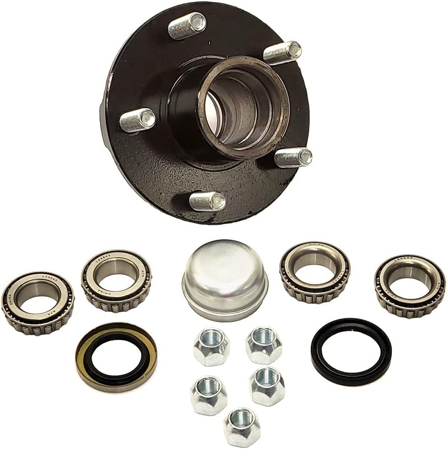
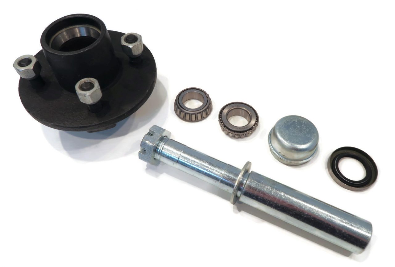
China Good quality Trailer Parts 5X4.5″ Trailer Hubs Trailer Idler Hub Non-Brake Wheel Hub Kit with Bearing and Spindle with Best Sales
Product Description
Product Description
Product Parameters
Packaging & Shipping
Our Advantages
Company Profile HangZhou Tsingleader Industry Co., Ltd. is located in the beautiful HangZhou city. We specialize in the production of trailer parts, axle and transmission of engineering machinery and special engineering and agricultural machinery.
Screw Sizes and Their UsesScrews have different sizes and features. This article will discuss screw sizes and their uses. There are 2 main types: right-handed and left-handed screw shafts. Each screw features a point that drills into the object. Flat tipped screws, on the other hand, need a pre-drilled hole. These screw sizes are determined by the major and minor diameters. To determine which size of screw you need, measure the diameter of the hole and the screw bolt’s thread depth. The major diameter of a screw shaftThe major diameter of a screw shaft is the distance from the outer edge of the thread on 1 side to the tip of the other. The minor diameter is the inner smooth part of the screw shaft. The major diameter of a screw is typically between 2 and 16 inches. A screw with a pointy tip has a smaller major diameter than 1 without. In addition, a screw with a larger major diameter will have a wider head and drive. The pitch diameter of a screw shaftWhen choosing the appropriate screw, it is important to know its pitch diameter and pitch line. The pitch line designates the distance between adjacent thread sides. The pitch diameter is also known as the mean area of the screw shaft. Both of these dimensions are important when choosing the correct screw. A screw with a pitch of 1/8 will have a mechanical advantage of 6.3. For more information, consult an application engineer at Roton. The thread depth of a screw shaftOften referred to as the major diameter, the thread depth is the outermost diameter of the screw. To measure the thread depth of a screw, use a steel rule, micrometer, or caliper. In general, the first number in the thread designation indicates the major diameter of the thread. If a section of the screw is worn, the thread depth will be smaller, and vice versa. Therefore, it is good practice to measure the section of the screw that receives the least amount of use. The lead of a screw shaftPitch and lead are 2 measurements of a screw’s linear distance per turn. They’re often used interchangeably, but their definitions are not the same. The difference between them lies in the axial distance between adjacent threads. For single-start screws, the pitch is equal to the lead, while the lead of a multi-start screw is greater than the pitch. This difference is often referred to as backlash. The thread angle of a screw shaftThe angle between the axes of a thread and the helix of a thread is called the thread angle. A unified thread has a 60-degree angle in all directions. Screws can have either a tapped hole or a captive screw. The screw pitch is measured in millimeters (mm) and is usually equal to the screw major diameter. In most cases, the thread angle will be equal to 60-degrees. The tapped hole (or nut) into which the screw fitsA screw can be re-threaded without having to replace it altogether. The process is different than that of a standard bolt, because it requires threading and tapping. The size of a screw is typically specified by its major and minor diameters, which is the inside distance between threads. The thread pitch, which is the distance between each thread, is also specified. Thread pitch is often expressed in threads per inch.
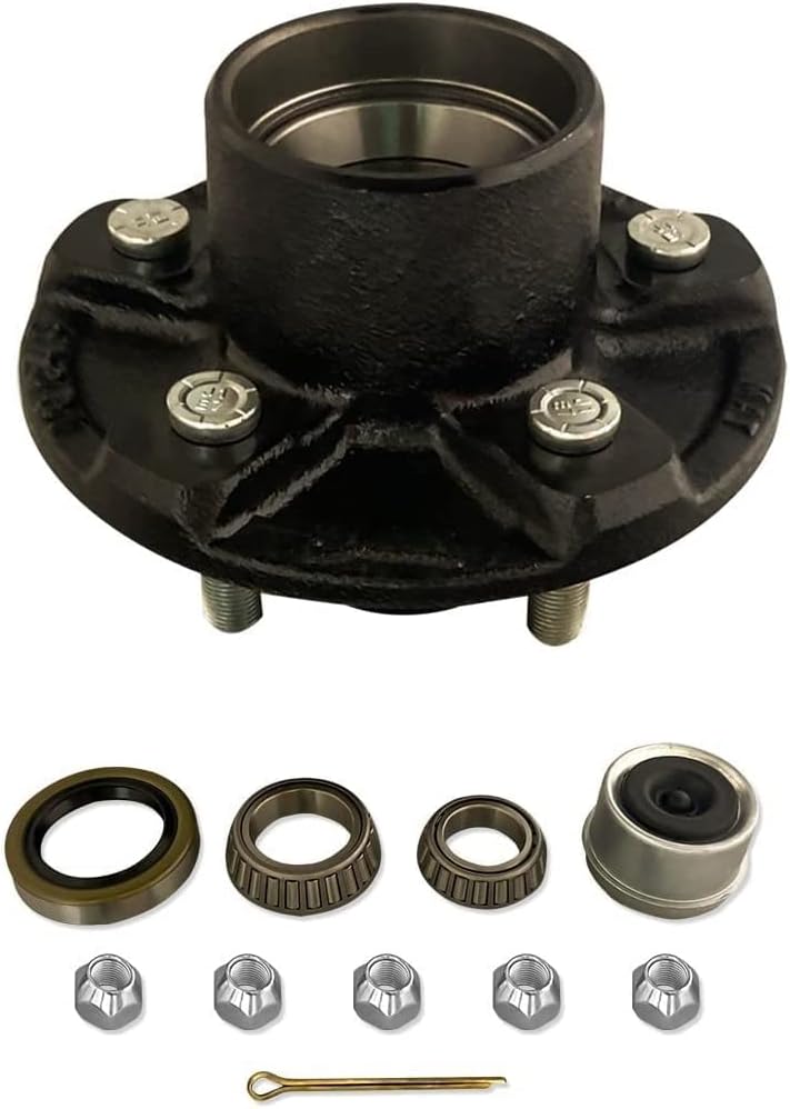
China Good quality Trailer Parts 5X5.5″ Trailer Hubs Trailer Idler Hub Non-Brake Wheel Hub Kit with Bearing and Spindle with Great quality
Product Description
Product Description
Product Parameters
Packaging & Shipping
Our Advantages
Company Profile HangZhou Tsingleader Industry Co., Ltd. is located in the beautiful HangZhou city. We specialize in the production of trailer parts, axle and transmission of engineering machinery and special engineering and agricultural machinery.
Analytical Approaches to Estimating Contact Pressures in Spline CouplingsA spline coupling is a type of mechanical connection between 2 rotating shafts. It consists of 2 parts – a coupler and a coupling. Both parts have teeth which engage and transfer loads. However, spline couplings are typically over-dimensioned, which makes them susceptible to fatigue and static behavior. Wear phenomena can also cause the coupling to fail. For this reason, proper spline coupling design is essential for achieving optimum performance. Modeling a spline couplingSpline couplings are becoming increasingly popular in the aerospace industry, but they operate in a slightly misaligned state, causing both vibrations and damage to the contact surfaces. To solve this problem, this article offers analytical approaches for estimating the contact pressures in a spline coupling. Specifically, this article compares analytical approaches with pure numerical approaches to demonstrate the benefits of an analytical approach. Creating a spline coupling model 20The spline coupling model 20 is created by a product model software program 10. The software validates the spline coupling model against a knowledge base of configuration-dependent specification constraints and relationships. This report is then input to the ANSYS stress analyzer program. It lists the spline coupling model 20’s geometric configurations and specification values for each feature. The spline coupling model 20 is automatically recreated every time the configuration or performance specifications of the spline coupling model 20 are modified. Analysing a spline coupling model 20An analysis of a spline coupling model consists of inputting its configuration and performance specifications. These specifications may be generated from another computer program. The product model software program 10 then uses its internal knowledge base of configuration dependent specification relationships and constraints to create a valid three-dimensional parametric model 20. This model contains information describing the number and types of spline teeth 32, snaps 34, and shoulder 36. Misalignment of a spline couplingA study aimed to investigate the position of the resultant contact force in a spline coupling engaging teeth under a steady torque and rotating misalignment. The study used numerical methods based on Finite Element Method (FEM) models. It produced numerical results for nominal conditions and parallel offset misalignment. The study considered 2 levels of misalignment – 0.02 mm and 0.08 mm – with different loading levels.
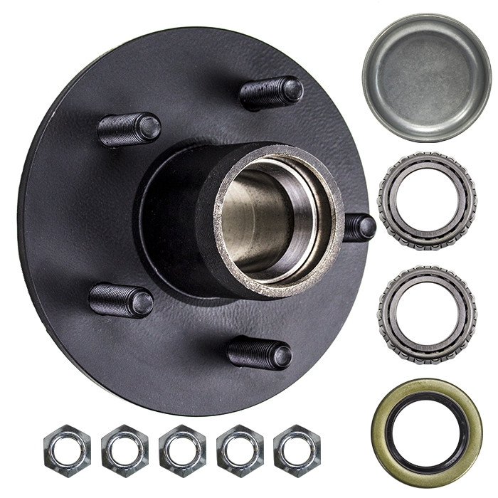
China factory Trailer Parts 6X5.5″ Trailer Hubs Trailer Idler Hub Non-Brake Wheel Hub Kit with Bearing and Spindle with high quality
Product Description
Product Description
Product Parameters
Packaging & Shipping
Our Advantages
Company Profile HangZhou Tsingleader Industry Co., Ltd. is located in the beautiful HangZhou city. We specialize in the production of trailer parts, axle and transmission of engineering machinery and special engineering and agricultural machinery.
Screws and Screw ShaftsA screw is a mechanical device that holds objects together. Screws are usually forged or machined. They are also used in screw jacks and press-fitted vises. Their self-locking properties make them a popular choice in many different industries. Here are some of the benefits of screws and how they work. Also read about their self-locking properties. The following information will help you choose the right screw for your application. Machined screw shaftA machined screw shaft can be made of various materials, depending on the application. Screw shafts can be made from stainless steel, brass, bronze, titanium, or iron. Most manufacturers use high-precision CNC machines or lathes to manufacture these products. These products come in many sizes and shapes, and they have varying applications. Different materials are used for different sizes and shapes. Here are some examples of what you can use these screws for: Ball screw nutWhen choosing a Ball screw nut for a screw shaft, it is important to consider the critical speed of the machine. This value excites the natural frequency of a screw and determines how fast it can be turned. In other words, it varies with the screw diameter and unsupported length. It also depends on the screw shaft’s diameter and end fixity. Depending on the application, the nut can be run at a maximum speed of about 80% of its theoretical critical speed. Self-locking property of screw shaftA self-locking screw is 1 that is capable of rotating without the use of a lock washer or bolt. This property is dependent on a number of factors, but 1 of them is the pitch angle of the thread. A screw with a small pitch angle is less likely to self-lock, while a large pitch angle is more likely to spontaneously rotate. The limiting angle of a self-locking thread can be calculated by calculating the torque Mkdw at which the screw is first released. Materials used to manufacture screw shaftMany materials are commonly used to manufacture screw shafts. The most common are steel, stainless steel, brass, bronze, and titanium. These materials have advantages and disadvantages that make them good candidates for screw production. Some screw types are also made of copper to fight corrosion and ensure durability over time. Other materials include nylon, Teflon, and aluminum. Brass screws are lightweight and have aesthetic appeal. The choice of material for a screw shaft depends on the use it will be made for.
China OEM Auto Parts Wheel Hub Bearing Front Axle Assembly Kit 31206872888 31204081309 31206775771 with Good quality
Product Description
Auto parts wheel hub bearing front axle assembly kit 3120687
MORE PRODUCT
ABOUT US Our main business is ignition coil, spark plugs, auto sensors, air filter, fuel filter, Brake pad, VVT valve ,EGR valve , Steering rack and so on. we had 5 years of experience in this area. We can provide more than 2,000 kinds of products for various brands of vehicles. We are looking forward to trading with overseas customers on the basis of equality and mutual benefit and CZPT benefit cooperation partnership. Certifications
FAQ
|


| Name | wheel hub bearings 3748.88 |
| Material | steel GCr15, 65Mn, or 55 |
| Application car makes | CITROEN/P-EUGEOT: |
| Size | ID: 32mm OD: 129 mm Height: 61 mm |
| Holes | 4 Holes |
| Weight | 0.38 kg |
| Brand | SI, PPB, or customized |
| Packing | Neutral, our brand packing or customized |
| OEM replacement | Yes |
| Manufacture place | ZHangZhoug, China |
| MOQ | 100 PCS |
| Warranty | 1 year or 40,000-50,000 KMS |
| Certificate | ISO9001:2015 |
| Payment | T/T, PayPal, Alibaba |
OEM:
CITROEN/P-EUGEOT: 3748.88
Other Ref.:
F-AG :
FEBI BILSTEIN : 47833
GSP : 9232571
GSP : 9232571K
MOOG : PE-WB-11407
OPTIMAL : 657146
S-KF : VKBA6500
SNR : R159.50
Application:
CITROEN BERLINGO / BERLINGO FIRST Box 1996-2011
CITROEN XSARA PICASSO 1999-2011
P-EUGEOT PARTNER 1996-2015
Other types(contact us for more models):
| S-KF VKBA Code | Application |
| VKBA 6896 | S-UBARU |
| VKBA 6897 | S-UBARU |
| VKBA 6898 | TOYOTA |
| VKBA 6900 | TOYOTA |
| VKBA 6901 | TOYOTA |
| VKBA 6905 | HYUNDAI,KIA |
| VKBA 6906 | L EXUS,TOYOTA |
| VKBA 6907 | L EXUS,TOYOTA |
| VKBA 6908 | TOYOTA |
| VKBA 6909 | L EXUS,TOYOTA |
| VKBA 6910 | TOYOTA |
| VKBA 6913 | MITSUBISHI |
| VKBA 6914 | MITSUBISHI |
| VKBA 6915 | MITSUBISHI |
| VKBA 6917 | HONDA |
| VKBA 6920 | DAIHATSU,TOYOTA |
| VKBA 6921 | DAIHATSU |
| VKBA 6923 | HYUNDAI,KIA |
| VKBA 6924 | TOYOTA |
| VKBA 6926 | MITSUBISHI |
| VKBA 6927 | MITSUBISHI |
| VKBA 6928 | MITSUBISHI |
| VKBA 6931 | HYUNDAI,KIA |
| VKBA 6938 | HYUNDAI |
| VKBA 6939 | HYUNDAI |
| VKBA 6940 | HYUNDAI |
| VKBA 6941 | HYUNDAI |
| VKBA 6942 | HYUNDAI |
| VKBA 6943 | HYUNDAI,KIA |
| VKBA 6944 | KIA |
| VKBA 6948 | HYUNDAI,KIA |
| VKBA 6949 | HYUNDAI |
| VKBA 6950 | HYUNDAI,KIA |
| VKBA 6953 | L EXUS |
| VKBA 6954 | L EXUS |
| VKBA 6955 | L EXUS |
| VKBA 6956 | HYUNDAI,KIA,TOYOTA |
| VKBA 6959 | L EXUS |
| VKBA 6961 | L EXUS |
| VKBA 6963 | L EXUS,TOYOTA |
| VKBA 6964 | MITSUBISHI |
| VKBA 6966 | DAIHATSU |
| VKBA 6967 | DAIHATSU |
| VKBA 6968 | DAIHATSU |
| VKBA 6972 | MAZDA |
| VKBA 6975 | SUZUKI |
| VKBA 6976 | SUZUKI |
| VKBA 6978 | SUZUKI |
| VKBA 6979 | SUZUKI |
| VKBA 6980 | SUZUKI |
| VKBA 6981 | NISSAN |
| VKBA 6984 | NISSAN |
| VKBA 6985 | NISSAN |
| VKBA 6990 | CHEVROLET |
| VKBA 6991 | HONDA |
| VKBA 6996 | NISSAN,R-ENAULT |
| VKBA 6997 | NISSAN,R-ENAULT |
| VKBA 6998 | NISSAN,R-ENAULT |
| VKBA 6999 | NISSAN |
| VKBA 713 | MITSUBISHI |
| VKBA 715 | MITSUBISHI |
| VKBA 717 | MAZDA |
| VKBA 719 | V-OLVO |
| VKBA 725 | ALFA ROMEO |
| VKBA 727 | AUSTIN |
| VKBA 728 | CITROËN,P-EUGEOT,TALBOT |
| VKBA 730 | AUSTIN,ROVER |
| VKBA 732 | V-OLVO |
| VKBA 733 | V-OLVO |
| VKBA 734 | FIAT,LXIHU (WEST LAKE) DIS.A,SEAT |
| VKBA 736 | O-PEL,VAUXHALL |
| VKBA 739 | MAZDA |
| VKBA 740 | FORD |
| VKBA 7400 | CHEVROLET,DAEWOO |
| VKBA 7401 | CHEVROLET,DAEWOO |
| VKBA 7403 | NISSAN |
| VKBA 7405 | MITSUBISHI |
| VKBA 7406 | MITSUBISHI |
| VKBA 7407 | MITSUBISHI |
| VKBA 7408 | CITROËN,DODGE,MITSUBISHI, P-EUGEOT |
| VKBA 7409 | CITROËN,MITSUBISHI,P-EUGEOT |
| VKBA 741 | FORD |
| VKBA 7410 | MITSUBISHI |
| VKBA 7412 | MITSUBISHI |
| VKBA 7413 | MITSUBISHI |
| VKBA 7414 | HYUNDAI,KIA |
| VKBA 7417 | MITSUBISHI |
| VKBA 7418 | NISSAN |
| VKBA 7419 | CHEVROLET,DAEWOO |
| VKBA 7427 | TOYOTA |
| VKBA 743 | CITROËN,P-EUGEOT |
| VKBA 7430 | TOYOTA |
| VKBA 7435 | MITSUBISHI |
| VKBA 7437 | CHEVROLET,O-PEL,VAUXHALL |
| VKBA 7439 | CHEVROLET,O-PEL,VAUXHALL |
| VKBA 7440 | HONDA |
| VKBA 7441 | HONDA |
| VKBA 7446 | MAZDA |
| VKBA 7447 | HONDA |
| VKBA 7449 | MAZDA |
| VKBA 745 | SAAB |
| VKBA 7451 | MITSUBISHI |
| VKBA 7454 | HYUNDAI |
| VKBA 7455 | SUZUKI |
| VKBA 7456 | SUZUKI |
| VKBA 7458 | SUZUKI |
| VKBA 7459 | SUZUKI |
| VKBA 7460 | SUZUKI |
| VKBA 7461 | HYUNDAI |
| VKBA 7462 | TOYOTA |
| VKBA 7468 | MAZDA |
| VKBA 7469 | HONDA |
| VKBA 7470 | I SUZU |
| VKBA 7472 | I SUZU |
| VKBA 7474 | NISSAN |
| VKBA 7478 | I SUZU |
| VKBA 7479 | S-UBARU |
| VKBA 7482 | KIA |
| VKBA 7488 | KIA |
| VKBA 7489 | KIA |
| VKBA 749 | AUSTIN,ROVER |
| VKBA 7490 | HONDA |
| VKBA 7491 | HONDA |
| VKBA 7492 | CHEVROLET,O-PEL,VAUXHALL |
| VKBA 7493 | CHEVROLET,O-PEL,VAUXHALL |
| VKBA 7497 | TOYOTA |
| VKBA 7498 | NISSAN |
| VKBA 7505 | CITROËN,MITSUBISHI,P-EUGEOT |
| VKBA 751 | NISSAN |
| VKBA 752 | ALFA ROMEO,NISSAN |
| VKBA 7525 | SUZUKI |
| VKBA 7526 | O-PEL,SUZUKI,VAUXHALL |
| VKBA 7529 | TOYOTA |
| VKBA 753 | MAZDA |
| VKBA 7534 | MAZDA |
| VKBA 7536 | MAZDA |
| VKBA 7537 | MAZDA |
| VKBA 7538 | MAZDA |
| VKBA 754 | O-PEL,VAUXHALL |
| VKBA 7540 | HONDA |
Other Parts:
Wheel Bearings, wheel hub bearings, wheel hub assembly, Wheel Bearing Hub, Wheel Hubs, Wheel Bearing And Hub Assembly, Wheel Bearing Hub Assembly Front, Wheel Bearing Hub Assembly, Wheel Bearing & Hub Assembly, Right Front Hub Bearing Assembly, Abs Hub Bearing Assembly, Hub And Bearing Assembly Front, Left Front Hub Bearing Assembly, Hub Bearing Assembly, hub and bearing replacement, hub bearing assembly front, bearing assembly, Front Wheel Bearing and Hub Assembly, Front Wheel Drive Hub and Bearing Assembly, Front Axle Bearing & Hub Assembly, Front Bearing Hub Assembly, Front Wheel Hub And Bearing Assembly, Front Wheel Bearing Hub Assembly Replacement, front bearing hub replacement, front wheel bearing hub assembly, front wheel bearing hub replacement, rear wheel bearing, rear wheel hub, rear hub assembly, hub bearing assembly rear, rear axle bearing and hubs
SI&PPB bearing has a plant area of 50,000 square meters, assets of RMB180 million, 500 employees, and 150 professional and technical personnel. The company uses high-quality GCR15 as its raw materials and uses Austenite heat treatment to ensure the service life of the products.
“The factory produces series models of mechanical clutch release bearings, belt tension wheel units, wheel bearings, and wheel bearing repair kits.
Partial products are produced by professional outsourcing factories, and the company’s testing center provides professional testing to ensure that the products meet the drawings or customer’s requirements.”
Packing:
FAQ:
Q1.What is your shipping logistic?
Re: DHL, TNT, FedEx express, by air/sea/train.
Q2:What’s the MOQ?
Re: For the wheel hub bearing repair kit. The MOQ is always 50 sets. If ordering together with other models, small quantities can be organized. But need more time due to the production schedule.
Q3. What are your goods of packing?
Re: Generally, our goods will be packed in Neutral white or brown boxes for the hub bearing unit. Our brand packing SI & CZPT are offered. If you have any other packing requests, we shall also handle them.
Q4. What is your sample policy?
Re: We can supply the sample if we have ready parts in stock.
Q5. Do you have any certificates?
Re: Yes, we have the certificate of ISO9001:2015.
Q6:Any warranty of your products.
Re: Sure, We are offering a guaranty for 12 months or 40,000-50,000 km for the aftermarket.
Driveshaft structure and vibrations associated with it
The structure of the drive shaft is critical to its efficiency and reliability. Drive shafts typically contain claw couplings, rag joints and universal joints. Other drive shafts have prismatic or splined joints. Learn about the different types of drive shafts and how they work. If you want to know the vibrations associated with them, read on. But first, let’s define what a driveshaft is.
transmission shaft
As the demand on our vehicles continues to increase, so does the demand on our drive systems. Higher CO2 emission standards and stricter emission standards increase the stress on the drive system while improving comfort and shortening the turning radius. These and other negative effects can place significant stress and wear on components, which can lead to driveshaft failure and increase vehicle safety risks. Therefore, the drive shaft must be inspected and replaced regularly.
Depending on your model, you may only need to replace 1 driveshaft. However, the cost to replace both driveshafts ranges from $650 to $1850. Additionally, you may incur labor costs ranging from $140 to $250. The labor price will depend on your car model and its drivetrain type. In general, however, the cost of replacing a driveshaft ranges from $470 to $1850.
Regionally, the automotive driveshaft market can be divided into 4 major markets: North America, Europe, Asia Pacific, and Rest of the World. North America is expected to dominate the market, while Europe and Asia Pacific are expected to grow the fastest. Furthermore, the market is expected to grow at the highest rate in the future, driven by economic growth in the Asia Pacific region. Furthermore, most of the vehicles sold globally are produced in these regions.
The most important feature of the driveshaft is to transfer the power of the engine to useful work. Drive shafts are also known as propeller shafts and cardan shafts. In a vehicle, a propshaft transfers torque from the engine, transmission, and differential to the front or rear wheels, or both. Due to the complexity of driveshaft assemblies, they are critical to vehicle safety. In addition to transmitting torque from the engine, they must also compensate for deflection, angular changes and length changes.
type
Different types of drive shafts include helical shafts, gear shafts, worm shafts, planetary shafts and synchronous shafts. Radial protruding pins on the head provide a rotationally secure connection. At least 1 bearing has a groove extending along its circumferential length that allows the pin to pass through the bearing. There can also be 2 flanges on each end of the shaft. Depending on the application, the shaft can be installed in the most convenient location to function.
Propeller shafts are usually made of high-quality steel with high specific strength and modulus. However, they can also be made from advanced composite materials such as carbon fiber, Kevlar and fiberglass. Another type of propeller shaft is made of thermoplastic polyamide, which is stiff and has a high strength-to-weight ratio. Both drive shafts and screw shafts are used to drive cars, ships and motorcycles.
Sliding and tubular yokes are common components of drive shafts. By design, their angles must be equal or intersect to provide the correct angle of operation. Unless the working angles are equal, the shaft vibrates twice per revolution, causing torsional vibrations. The best way to avoid this is to make sure the 2 yokes are properly aligned. Crucially, these components have the same working angle to ensure smooth power flow.
The type of drive shaft varies according to the type of motor. Some are geared, while others are non-geared. In some cases, the drive shaft is fixed and the motor can rotate and steer. Alternatively, a flexible shaft can be used to control the speed and direction of the drive. In some applications where linear power transmission is not possible, flexible shafts are a useful option. For example, flexible shafts can be used in portable devices.
put up
The construction of the drive shaft has many advantages over bare metal. A shaft that is flexible in multiple directions is easier to maintain than a shaft that is rigid in other directions. The shaft body and coupling flange can be made of different materials, and the flange can be made of a different material than the main shaft body. For example, the coupling flange can be made of steel. The main shaft body is preferably flared on at least 1 end, and the at least 1 coupling flange includes a first generally frustoconical projection extending into the flared end of the main shaft body.
The normal stiffness of fiber-based shafts is achieved by the orientation of parallel fibers along the length of the shaft. However, the bending stiffness of this shaft is reduced due to the change in fiber orientation. Since the fibers continue to travel in the same direction from the first end to the second end, the reinforcement that increases the torsional stiffness of the shaft is not affected. In contrast, a fiber-based shaft is also flexible because it uses ribs that are approximately 90 degrees from the centerline of the shaft.
In addition to the helical ribs, the drive shaft 100 may also contain reinforcing elements. These reinforcing elements maintain the structural integrity of the shaft. These reinforcing elements are called helical ribs. They have ribs on both the outer and inner surfaces. This is to prevent shaft breakage. These elements can also be shaped to be flexible enough to accommodate some of the forces generated by the drive. Shafts can be designed using these methods and made into worm-like drive shafts.
vibration
The most common cause of drive shaft vibration is improper installation. There are 5 common types of driveshaft vibration, each related to installation parameters. To prevent this from happening, you should understand what causes these vibrations and how to fix them. The most common types of vibration are listed below. This article describes some common drive shaft vibration solutions. It may also be beneficial to consider the advice of a professional vibration technician for drive shaft vibration control.
If you’re not sure if the problem is the driveshaft or the engine, try turning on the stereo. Thicker carpet kits can also mask vibrations. Nonetheless, you should contact an expert as soon as possible. If vibration persists after vibration-related repairs, the driveshaft needs to be replaced. If the driveshaft is still under warranty, you can repair it yourself.
CV joints are the most common cause of third-order driveshaft vibration. If they are binding or fail, they need to be replaced. Alternatively, your CV joints may just be misaligned. If it is loose, you can check the CV connector. Another common cause of drive shaft vibration is improper assembly. Improper alignment of the yokes on both ends of the shaft can cause them to vibrate.
Incorrect trim height can also cause driveshaft vibration. Correct trim height is necessary to prevent drive shaft wobble. Whether your vehicle is new or old, you can perform some basic fixes to minimize problems. One of these solutions involves balancing the drive shaft. First, use the hose clamps to attach the weights to it. Next, attach an ounce of weight to it and spin it. By doing this, you minimize the frequency of vibration.
cost
The global driveshaft market is expected to exceed (xxx) million USD by 2028, growing at a compound annual growth rate (CAGR) of XX%. Its soaring growth can be attributed to several factors, including increasing urbanization and R&D investments by leading market players. The report also includes an in-depth analysis of key market trends and their impact on the industry. Additionally, the report provides a comprehensive regional analysis of the Driveshaft Market.
The cost of replacing the drive shaft depends on the type of repair required and the cause of the failure. Typical repair costs range from $300 to $750. Rear-wheel drive cars usually cost more. But front-wheel drive vehicles cost less than four-wheel drive vehicles. You may also choose to try repairing the driveshaft yourself. However, it is important to do your research and make sure you have the necessary tools and equipment to perform the job properly.
The report also covers the competitive landscape of the Drive Shafts market. It includes graphical representations, detailed statistics, management policies, and governance components. Additionally, it includes a detailed cost analysis. Additionally, the report presents views on the COVID-19 market and future trends. The report also provides valuable information to help you decide how to compete in your industry. When you buy a report like this, you are adding credibility to your work.
A quality driveshaft can improve your game by ensuring distance from the tee and improving responsiveness. The new material in the shaft construction is lighter, stronger and more responsive than ever before, so it is becoming a key part of the driver. And there are a variety of options to suit any budget. The main factor to consider when buying a shaft is its quality. However, it’s important to note that quality doesn’t come cheap and you should always choose an axle based on what your budget can handle.
China Best Sales Rear Axle Ball Bearing Wheel Bearing Kit Vkba6809 52750-1c100 52750-1g101 for Hyundai Accent and for KIA Picanto near me factory
Product Description
Basic information:
| Description | Rear Axle Ball Bearing Wheel Bearing Kit VKBA6809 52750-1C100 52750-1G101 For HYUNDAI ACCENT And For KIA PICANTO |
| Material | Chrome steel Gcr15 |
| Application | For Hyundai & KIA |
| Position | Rear wheel |
| With ABS | Yes |
| Bolts | 4 bolts |
| Weight | 3.1 kg |
| Brand | SI, PPB, or customized |
| Packing | Neutral, SI, PPB brand packing or customized |
| OEM/ODM service | Yes |
| Manufacture place | ZHangZhoug, China |
| MOQ | 50 PCS |
| OEM replacement | Yes |
| Inspection | 100% |
| Warranty | 1 year or 40,000-50,000 KMS |
| Certificate | ISO9001:2015 TS16949 |
| Payment | T/T, PayPal, Alibaba |
| Advantages | Specialized features/benefits Less vibration and noise Less energy consumption Quality approvals Improved fatigue life Reduced noise vibration Super finished raceways |
Detailed pictures:
O.E.:
52750-5710
52750-1C100
52750-1C200
52750-1G100
52750-1G101
Ref.:
31403
HY-WB-11814
922406
VKBA 6809
R184.18
R189.23
Application:
For HYUNDAI ACCENT III (MC) 2005-2571
For HYUNDAI ACCENT III Saloon (MC) 2005-2012
For HYUNDAI GETZ (TB) 2002-2571
For HYUNDAI i10 (PA) 2008-2017
For HYUNDAI i20 (PB, PBT) 2008-2015
For KIA PICANTO (SA) 2004-
For KIA RIO II (JB) 2005-
Packing and Delivery:
Work shop:
Exhibitions:
FAQ:
Q1.What is your shipping logistic?
Re: DHL, TNT, FedEx express, by air/sea/train.
Q2:What’s the MOQ?
Re: For the wheel hub assembly. The MOQ is always 50 sets. If ordering together with other models, small quantities can be organized. But need more time due to the production schedule.
Q3. What are your goods of packing?
Re: Generally, our goods will be packed in Neutral white or brown boxes for the hub bearing unit. Our brand packing SI & CZPT are offered. If you have any other packing requests, we shall also handle them.
Q4. What is your sample policy?
Re: We can supply the sample if we have ready parts in stock.
Q5. Do you have any certificates?
Re: Yes, we have the certificate of ISO9001:2015.
Q6:Any warranty of your products.
Re: Sure, We are offering a guarantee for 12 months or 40,000-50,000 km for the aftermarket.
Q7: How can I make an inquiry?
Re: You can contact us by email, telephone, WhatsApp, , etc.
Q8: How long can reply inquiry?
Re: Within 24 hours.
Q9: What’s the delivery time?
Re: Ready stock 10-15 days, production for 30 to 45 days.
Q10: How do you maintain our good business relationship?
Re: 1. Keep stable, reliable quality, competitive price to ensure our customer’s benefit;
2. Optimal lead time.
3. Keep customers updated about the new goods.
4. Make customers satisfaction as our main goal.
Q11: Can we visit the company & factory?
Re: Yes, welcome for your visit & business discussion.
The Different Types of Splines in a Splined Shaft
A splined shaft is a machine component with internal and external splines. The splines are formed in 4 different ways: Involute, Parallel, Serrated, and Ball. You can learn more about each type of spline in this article. When choosing a splined shaft, be sure to choose the right 1 for your application. Read on to learn about the different types of splines and how they affect the shaft’s performance.
Involute splines
Involute splines in a splined shaft are used to secure and extend mechanical assemblies. They are smooth, inwardly curving grooves that resist separation during operation. A shaft with involute splines is often longer than the shaft itself. This feature allows for more axial movement. This is beneficial for many applications, especially in a gearbox.
The involute spline is a shaped spline, similar to a parallel spline. It is angled and consists of teeth that create a spiral pattern that enables linear and rotatory motion. It is distinguished from other splines by the serrations on its flanks. It also has a flat top. It is a good option for couplers and other applications where angular movement is necessary.
Involute splines are also called involute teeth because of their shape. They are flat on the top and curved on the sides. These teeth can be either internal or external. As a result, involute splines provide greater surface contact, which helps reduce stress and fatigue. Regardless of the shape, involute splines are generally easy to machine and fit.
Involute splines are a type of splines that are used in splined shafts. These splines have different names, depending on their diameters. An example set of designations is for a 32-tooth male spline, a 2,500-tooth module, and a 30 degree pressure angle. An example of a female spline, a fillet root spline, is used to describe the diameter of the splined shaft.
The effective tooth thickness of splines is dependent on the number of keyways and the type of spline. Involute splines in splined shafts should be designed to engage 25 to 50 percent of the spline teeth during the coupling. Involute splines should be able to withstand the load without cracking.
Parallel splines
Parallel splines are formed on a splined shaft by putting 1 or more teeth into another. The male spline is positioned at the center of the female spline. The teeth of the male spline are also parallel to the shaft axis, but a common misalignment causes the splines to roll and tilt. This is common in many industrial applications, and there are a number of ways to improve the performance of splines.
Typically, parallel splines are used to reduce friction in a rotating part. The splines on a splined shaft are narrower on the end face than the interior, which makes them more prone to wear. This type of spline is used in a variety of industries, such as machinery, and it also allows for greater efficiency when transmitting torque.
Involute splines on a splined shaft are the most common. They have equally spaced teeth, and are therefore less likely to crack due to fatigue. They also tend to be easy to cut and fit. However, they are not the best type of spline. It is important to understand the difference between parallel and involute splines before deciding on which spline to use.
The difference between splined and involute splines is the size of the grooves. Involute splines are generally larger than parallel splines. These types of splines provide more torque to the gear teeth and reduce stress during operation. They are also more durable and have a longer life span. And because they are used on farm machinery, they are essential in this type of application.
Serrated splines
A Serrated Splined Shaft has several advantages. This type of shaft is highly adjustable. Its large number of teeth allows large torques, and its shorter tooth width allows for greater adjustment. These features make this type of shaft an ideal choice for applications where accuracy is critical. Listed below are some of the benefits of this type of shaft. These benefits are just a few of the advantages. Learn more about this type of shaft.
The process of hobbing is inexpensive and highly accurate. It is useful for external spline shafts, but is not suitable for internal splines. This type of process forms synchronized shapes on the shaft, reducing the manufacturing cycle and stabilizing the relative phase between spline and thread. It uses a grinding wheel to shape the shaft. CZPT Manufacturing has a large inventory of Serrated Splined Shafts.
The teeth of a Serrated Splined Shaft are designed to engage with the hub over the entire circumference of the shaft. The teeth of the shaft are spaced uniformly around the spline, creating a multiple-tooth point of contact over the entire length of the shaft. The results of these analyses are usually satisfactory. But there are some limitations. To begin with, the splines of the Serrated Splined Shaft should be chosen carefully. If the application requires large-scale analysis, it may be necessary to modify the design.
The splines of the Serrated Splined Shaft are also used for other purposes. They can be used to transmit torque to another device. They also act as an anti-rotational device and function as a linear guide. Both the design and the type of splines determine the function of the Splined Shaft. In the automobile industry, they are used in vehicles, aerospace, earth-moving machinery, and many other industries.
Ball splines
The invention relates to a ball-spinned shaft. The shaft comprises a plurality of balls that are arranged in a series and are operatively coupled to a load path section. The balls are capable of rolling endlessly along the path. This invention also relates to a ball bearing. Here, a ball bearing is 1 of the many types of gears. The following discussion describes the features of a ball bearing.
A ball-splined shaft assembly comprises a shaft with at least 1 ball-spline groove and a plurality of circumferential step grooves. The shaft is held in a first holding means that extends longitudinally and is rotatably held by a second holding means. Both the shaft and the first holding means are driven relative to 1 another by a first driving means. It is possible to manufacture a ball-splined shaft in a variety of ways.
A ball-splined shaft features a nut with recirculating balls. The ball-splined nut rides in these grooves to provide linear motion while preventing rotation. A splined shaft with a nut that has recirculating balls can also provide rotary motion. A ball splined shaft also has higher load capacities than a ball bushing. For these reasons, ball splines are an excellent choice for many applications.
In this invention, a pair of ball-spinned shafts are housed in a box under a carrier device 40. Each of the 2 shafts extends along a longitudinal line of arm 50. One end of each shaft is supported rotatably by a slide block 56. The slide block also has a support arm 58 that supports the center arm 50 in a cantilever fashion.
Sector no-go gage
A no-go gauge is a tool that checks the splined shaft for oversize. It is an effective way to determine the oversize condition of a splined shaft without removing the shaft. It measures external splines and serrations. The no-go gage is available in sizes ranging from 19mm to 130mm with a 25mm profile length.
The sector no-go gage has 2 groups of diametrally opposed teeth. The space between them is manufactured to a maximum space width and the tooth thickness must be within a predetermined tolerance. This gage would be out of tolerance if the splines were measured with a pin. The dimensions of this splined shaft can be found in the respective ANSI or DIN standards.
The go-no-go gage is useful for final inspection of thread pitch diameter. It is also useful for splined shafts and threaded nuts. The thread of a screw must match the contour of the go-no-go gage head to avoid a no-go condition. There is no substitute for a quality machine. It is an essential tool for any splined shaft and fastener manufacturer.
The NO-GO gage can detect changes in tooth thickness. It can be calibrated under ISO17025 standards and has many advantages over a non-go gage. It also gives a visual reference of the thickness of a splined shaft. When the teeth match, the shaft is considered ready for installation. It is a critical process. In some cases, it is impossible to determine the precise length of the shaft spline.
The 45-degree pressure angle is most commonly used for axles and torque-delivering members. This pressure angle is the most economical in terms of tool life, but the splines will not roll neatly like a 30 degree angle. The 45-degree spline is more likely to fall off larger than the other two. Oftentimes, it will also have a crowned look. The 37.5 degree pressure angle is a compromise between the other 2 pressure angles. It is often used when the splined shaft material is harder than usual.
China Best Sales Wheel Bearing Hub Kit for Nissan X-Trail Wheel Hub Bearing Assembly 40202-1ka0a 40202-Jg000 40202-Jg01A 40202-Jg01b 402022560r Vkba6996 near me factory
Product Description
Basic information:
| Description | Wheel Bearing Hub Kit For NISSAN X-TRAIL Wheel Hub Bearing Assembly 45712-1KA0A 45712-JGR VKBA6996 |
| Material | Chrome steel Gcr15 |
| Application | For NISSAN For RENAULT |
| Size | Rim Hole Number: 5 Flange Ø: 136 mm |
| Position | Front wheel hub |
| With ABS | with integrated ABS sensor |
| Bolts | 5 holes |
| Weight | 2.9 kg |
| Brand | SI, PPB, or customized |
| Packing | Neutral, SI, PPB brand packing or customized |
| OEM/ODM service | Yes |
| Manufacture place | ZHangZhoug, China |
| MOQ | 50 PCS |
| OEM replacement | Yes |
| Inspection | 100% |
| Warranty | 1 year or 40,000-50,000 KMS |
| Certificate | ISO9001:2015 TS16949 |
| Payment | T/T, PayPal, Alibaba |
Detailed pictures:
O.E.:
45712-1KA0A
45712-3PU0A
45712-BA60A
45712-JG000
45712-JG01A
45712-JG01B
457122560R
45712JY00A
Ref.:
F-AG:
F-AG:
GSP: 9329006
MOOG: NI-WB-11963
OPTIMAL: 701501
OPTIMAL: 961560
S-KF: VKBA 6996
SNR: R168.104
SNR: R168.131
SNR: R168.73
Application:
For NISSAN QASHQAI / QASHQAI +2 (J10, JJ10) (2007/02 – /)
For NISSAN X-TRAIL (T31) (2007/03 – 2013/11)
For RENAULT KOLEOS (HY_) (2008/09 – /)
Wheel Bearings, Wheel Hubs, Wheel Bearing And Hub Assembly, Right Front Hub Bearing Assembly, Wheel Bearing Hub Assembly Front, Front Wheel Hub And Bearing Assembly, Abs Hub Bearing Assembly, Wheel Bearing Hub Assembly, Hub And Bearing Assembly Front, Left Front Hub Bearing Assembly, Front Wheel Bearing Hub Assembly Replacement, Wheel Bearing & Hub Assembly, Hub Bearing Assembly
Packing and Delivery:
Work shop:
Exhibitions:
FAQ:
Q1.What is your shipping logistic?
Re: DHL, TNT, FedEx express, by air/sea/train.
Q2:What’s the MOQ?
Re: For the wheel hub assembly. The MOQ is always 50 sets. If ordering together with other models, small quantities can be organized. But need more time due to the production schedule.
Q3. What are your goods of packing?
Re: Generally, our goods will be packed in Neutral white or brown boxes for the hub bearing unit. Our brand packing SI & CZPT are offered. If you have any other packing requests, we shall also handle them.
Q4. What is your sample policy?
Re: We can supply the sample if we have ready parts in stock.
Q5. Do you have any certificates?
Re: Yes, we have the certificate of ISO9001:2015.
Q6:Any warranty of your products.
Re: Sure, We are offering a guarantee for 12 months or 40,000-50,000 km for the aftermarket.
Q7: How can I make an inquiry?
Re: You can contact us by email, telephone, WhatsApp, , etc.
Q8: How long can reply inquiry?
Re: Within 24 hours.
Q9: What’s the delivery time?
Re: Ready stock 10-15 days, production for 30 to 45 days.
Q10: How do you maintain our good business relationship?
Re: 1. Keep stable, reliable quality, competitive price to ensure our customer’s benefit;
2. Optimal lead time.
3. Keep customers updated about the new goods.
4. Make customers satisfaction as our main goal.
Q11: Can we visit the company & factory?
Re: Yes, welcome for your visit & business discussion.
What is a drive shaft?
If you notice a clicking noise while driving, it is most likely the driveshaft. An experienced auto mechanic will be able to tell you if the noise is coming from both sides or from 1 side. If it only happens on 1 side, you should check it. If you notice noise on both sides, you should contact a mechanic. In either case, a replacement driveshaft should be easy to find.
The drive shaft is a mechanical part
A driveshaft is a mechanical device that transmits rotation and torque from the engine to the wheels of the vehicle. This component is essential to the operation of any driveline, as the mechanical power from the engine is transmitted to the PTO (power take-off) shaft, which hydraulically transmits that power to connected equipment. Different drive shafts contain different combinations of joints to compensate for changes in shaft length and angle. Some types of drive shafts include connecting shafts, internal constant velocity joints, and external fixed joints. They also contain anti-lock system rings and torsional dampers to prevent overloading the axle or causing the wheels to lock.
Although driveshafts are relatively light, they need to handle a lot of torque. Torque applied to the drive shaft produces torsional and shear stresses. Because they have to withstand torque, these shafts are designed to be lightweight and have little inertia or weight. Therefore, they usually have a joint, coupling or rod between the 2 parts. Components can also be bent to accommodate changes in the distance between them.
The drive shaft can be made from a variety of materials. The most common material for these components is steel, although alloy steels are often used for high-strength applications. Alloy steel, chromium or vanadium are other materials that can be used. The type of material used depends on the application and size of the component. In many cases, metal driveshafts are the most durable and cheapest option. Plastic shafts are used for light duty applications and have different torque levels than metal shafts.
It transfers power from the engine to the wheels
A car’s powertrain consists of an electric motor, transmission, and differential. Each section performs a specific job. In a rear-wheel drive vehicle, the power generated by the engine is transmitted to the rear tires. This arrangement improves braking and handling. The differential controls how much power each wheel receives. The torque of the engine is transferred to the wheels according to its speed.
The transmission transfers power from the engine to the wheels. It is also called “transgender”. Its job is to ensure power is delivered to the wheels. Electric cars cannot drive themselves and require a gearbox to drive forward. It also controls how much power reaches the wheels at any given moment. The transmission is the last part of the power transmission chain. Despite its many names, the transmission is the most complex component of a car’s powertrain.
The driveshaft is a long steel tube that transmits mechanical power from the transmission to the wheels. Cardan joints connect to the drive shaft and provide flexible pivot points. The differential assembly is mounted on the drive shaft, allowing the wheels to turn at different speeds. The differential allows the wheels to turn at different speeds and is very important when cornering. Axles are also important to the performance of the car.
It has a rubber boot that protects it from dust and moisture
To keep this boot in good condition, you should clean it with cold water and a rag. Never place it in the dryer or in direct sunlight. Heat can deteriorate the rubber and cause it to shrink or crack. To prolong the life of your rubber boots, apply rubber conditioner to them regularly. Indigenous peoples in the Amazon region collect latex sap from the bark of rubber trees. Then they put their feet on the fire to solidify the sap.
it has a U-shaped connector
The drive shaft has a U-joint that transfers rotational energy from the engine to the axle. Defective gimbal joints can cause vibrations when the vehicle is in motion. This vibration is often mistaken for a wheel balance problem. Wheel balance problems can cause the vehicle to vibrate while driving, while a U-joint failure can cause the vehicle to vibrate when decelerating and accelerating, and stop when the vehicle is stopped.
The drive shaft is connected to the transmission and differential using a U-joint. It allows for small changes in position between the 2 components. This prevents the differential and transmission from remaining perfectly aligned. The U-joint also allows the drive shaft to be connected unconstrained, allowing the vehicle to move. Its main purpose is to transmit electricity. Of all types of elastic couplings, U-joints are the oldest.
Your vehicle’s U-joints should be inspected at least twice a year, and the joints should be greased. When checking the U-joint, you should hear a dull sound when changing gears. A clicking sound indicates insufficient grease in the bearing. If you hear or feel vibrations when shifting gears, you may need to service the bearings to prolong their life.
it has a slide-in tube
The telescopic design is a modern alternative to traditional driveshaft designs. This innovative design is based on an unconventional design philosophy that combines advances in material science and manufacturing processes. Therefore, they are more efficient and lighter than conventional designs. Slide-in tubes are a simple and efficient design solution for any vehicle application. Here are some of its benefits. Read on to learn why this type of shaft is ideal for many applications.
The telescopic drive shaft is an important part of the traditional automobile transmission system. These driveshafts allow linear motion of the 2 components, transmitting torque and rotation throughout the vehicle’s driveline. They also absorb energy if the vehicle collides. Often referred to as foldable driveshafts, their popularity is directly dependent on the evolution of the automotive industry.
It uses a bearing press to replace worn or damaged U-joints
A bearing press is a device that uses a rotary press mechanism to install or remove worn or damaged U-joints from a drive shaft. With this tool, you can replace worn or damaged U-joints in your car with relative ease. The first step involves placing the drive shaft in the vise. Then, use the 11/16″ socket to press the other cup in far enough to install the clips. If the cups don’t fit, you can use a bearing press to remove them and repeat the process. After removing the U-joint, use a grease nipple Make sure the new grease nipple is installed correctly.
Worn or damaged U-joints are a major source of driveshaft failure. If 1 of them were damaged or damaged, the entire driveshaft could dislocate and the car would lose power. Unless you have a professional mechanic doing the repairs, you will have to replace the entire driveshaft. Fortunately, there are many ways to do this yourself.
If any of these warning signs appear on your vehicle, you should consider replacing the damaged or worn U-joint. Common symptoms of damaged U-joints include rattling or periodic squeaking when moving, rattling when shifting, wobbling when turning, or rusted oil seals. If you notice any of these symptoms, take your vehicle to a qualified mechanic for a full inspection. Neglecting to replace a worn or damaged u-joint on the driveshaft can result in expensive and dangerous repairs and can cause significant damage to your vehicle.